|  |
 |
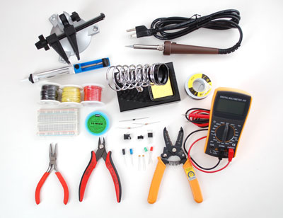
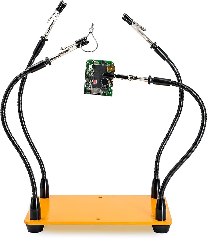
| Third hand Grip your pieces while you soldering |
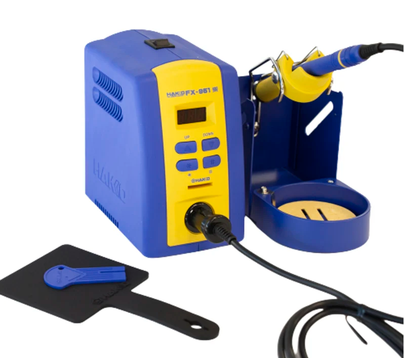
Soldering Iron Professional-style temperature-controlled iron |
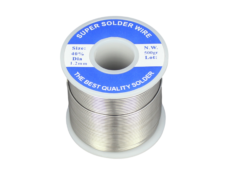
Solder |
 |
 |
 |
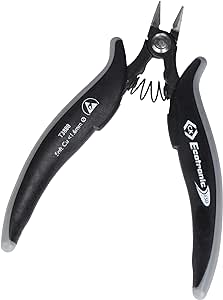
| Snip Trim leads after soldering / Pre-cut the plastic part before the desoldering |
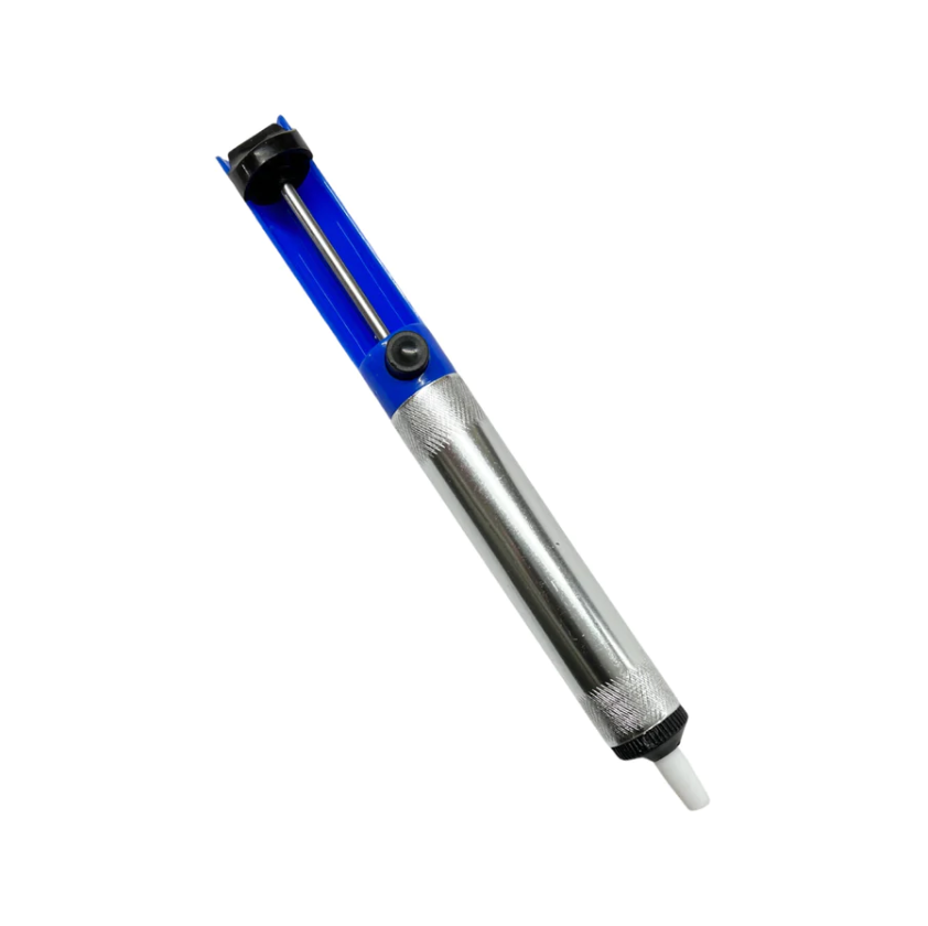
Soldering Sucker Remove excess solder / Des-older a joint |
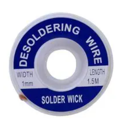
Solder Wick Clean excess solder / Soak up the molten solder |
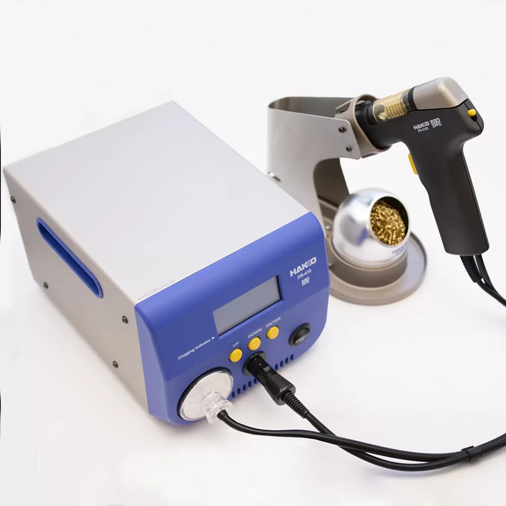 |
 | Desoldering gun Remove molten solder from a joint. |
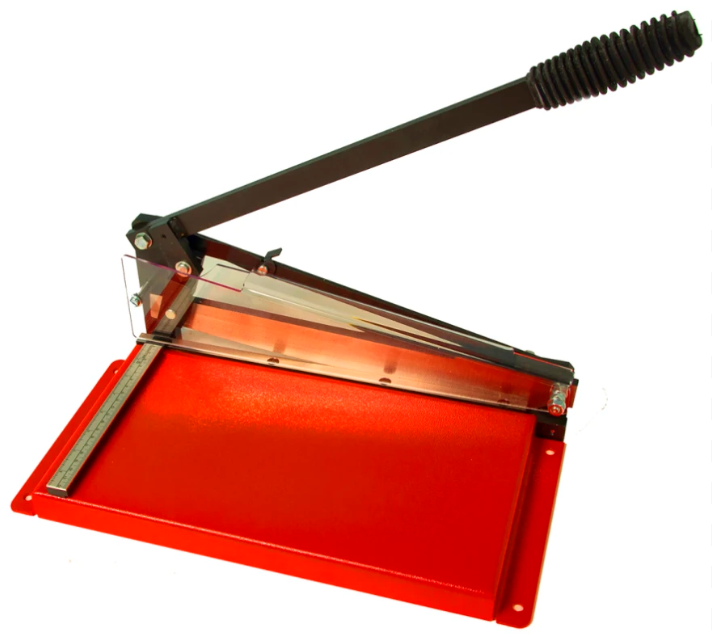
PCB Guillotine Cut the PCB board |
It's better to draw a diagram before you start, which could easily figure out how much stripboard you need (Don't waste!) and you can cut the board down to the size by the PCB Guillotine.
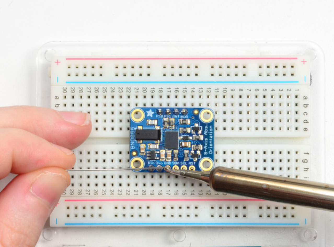
For the stripboard and protoboard, you need a third hand to provide the board moving around while soldering.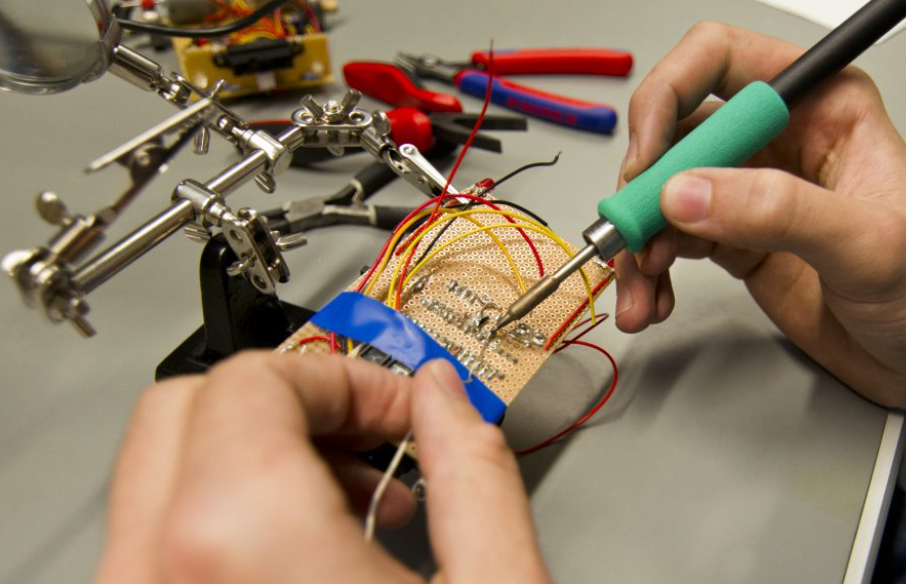 ## How to solder
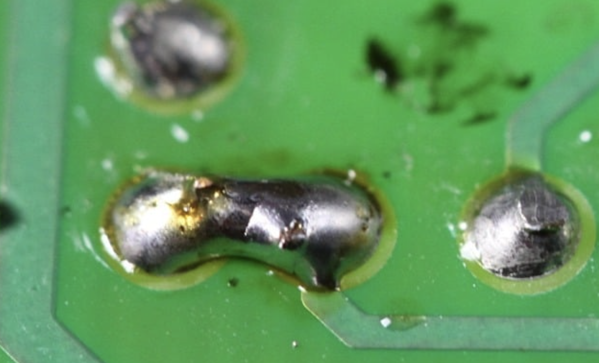
Once all of the components are immobilized, you are ready to soldering. It only takes 4 easy steps to get a nice solder joint. Here is a video for ["How to soldering properly!"](https://www.youtube.com/watch?v=QKbJxytERvg&t=196s)
## How to solder
Once all of the components are immobilized, you are ready to soldering. It only takes 4 easy steps to get a nice solder joint. Here is a video for ["How to soldering properly!"](https://www.youtube.com/watch?v=QKbJxytERvg&t=196s)
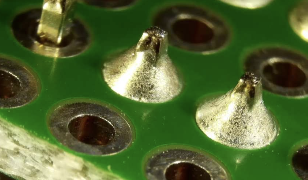
Make Sure there is no short circuit on your board before you power it!
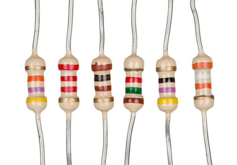 Resistors are electronic components that resist the flow of current. You will often find them in parts of circuits where you need to protect sensitive components (like LEDs) or measure something with changing resistance (like an light dependent resistor). You'll notice that we have lots of different kinds of resistors in the CCI -- that's because it can matter a lot what value of resistor you use. Resistors are numbered according to [orders of magnitude](https://en.wikipedia.org/wiki/Order_of_magnitude), and resistance is measured in Ohms (Ω). A resistor with a resistance of 1kΩ (1 kilo-ohm) has 1000 times more resistance than a 1Ω resistor, and 1000 times less than a 1MΩ resistor.
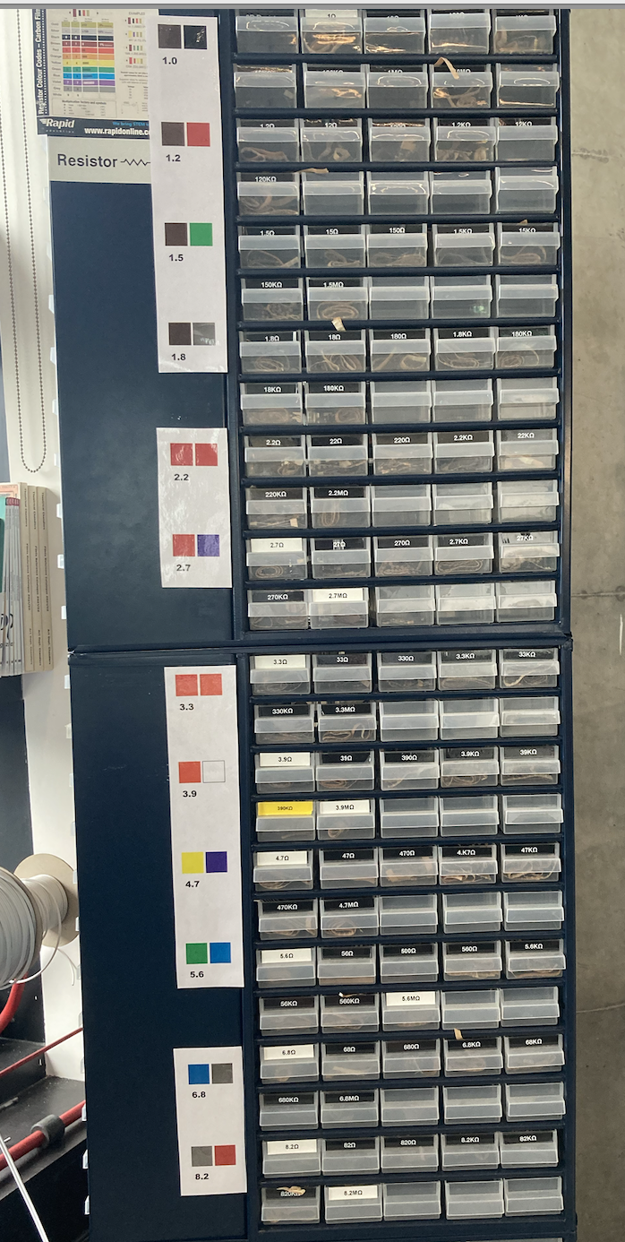 When you are making a circuit, it's important to get the correct resistor values. You can check these against the labels on the drawers, but you can also check this yourself -- all resistors have a pattern of stripes on them. Almost all the resistors we have are four-band -- so the first two stripes indicate the number value of the resistor, and the third the order of magnitude. There's a guide to decoding the stripes [here](https://byjus.com/physics/resistor-colour-codes/), and a chart guide below:
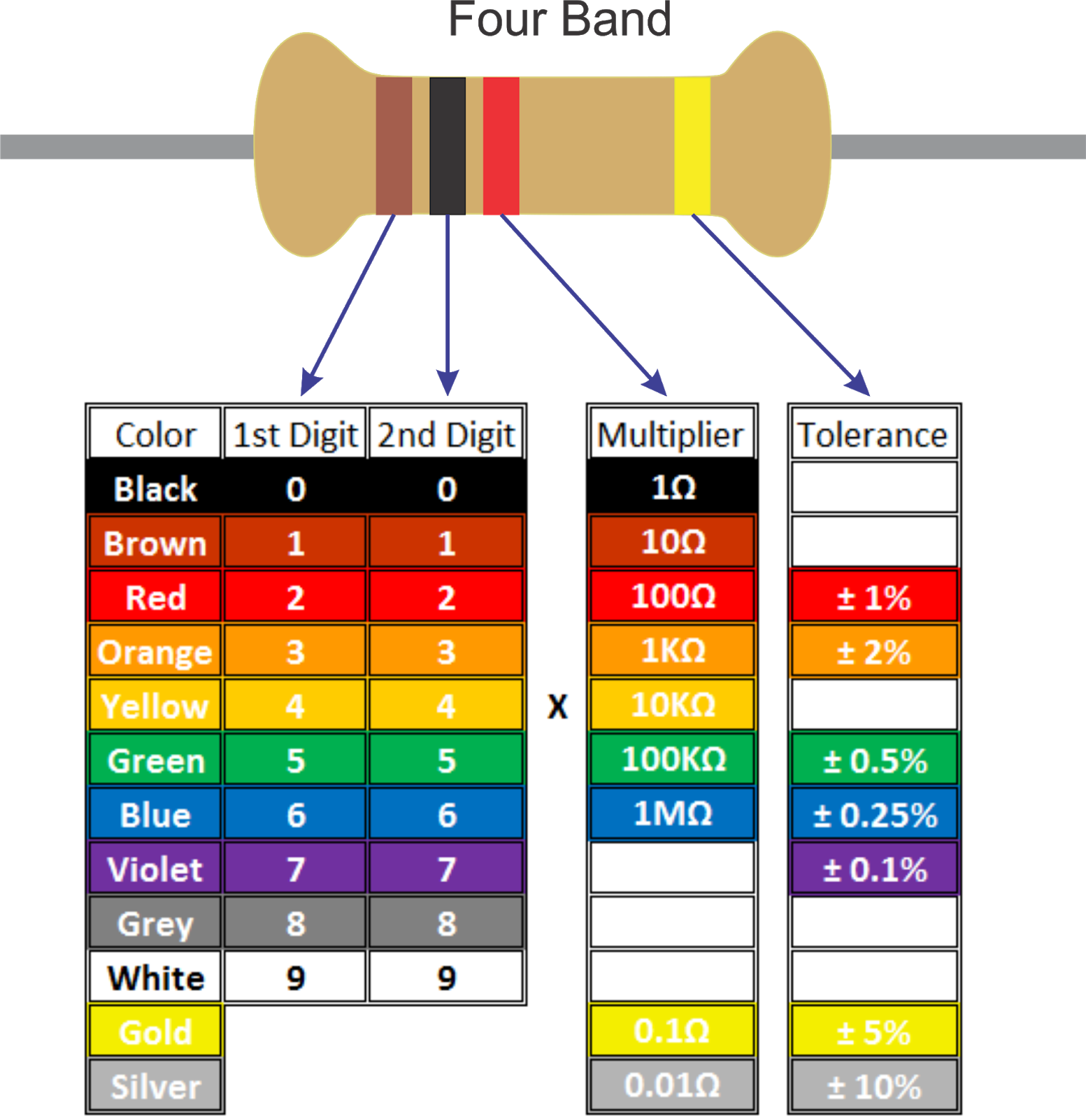 Note: In general the 3rd stripe (the order of magnitude) matters a lot more than the first two (which give you the number value). So if you need a 220Ω resistor but can't find one, a 270Ω or 180Ω resistor will probably be okay, but a 220kΩ resistor will be way too big for what you're trying to do.
The 4th band of a resistor indicates the tolerance. It's normally fine to ignore this, unless you need your value to be very precise (in which case pick one with a coloured band).
## Capacitors
Note: In general the 3rd stripe (the order of magnitude) matters a lot more than the first two (which give you the number value). So if you need a 220Ω resistor but can't find one, a 270Ω or 180Ω resistor will probably be okay, but a 220kΩ resistor will be way too big for what you're trying to do.
The 4th band of a resistor indicates the tolerance. It's normally fine to ignore this, unless you need your value to be very precise (in which case pick one with a coloured band).
## Capacitors
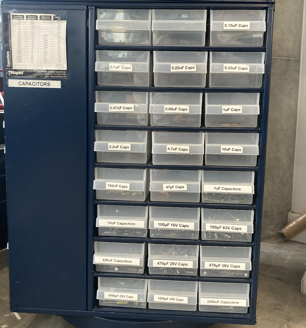 Capacitors are used to control *changing* electrical signals. You find them in circuits like filters, audio and radio circuits, and they are also used to balance out things like power supplies.
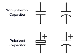
 We have two different kinds of capacitor: electrolytic, and ceramic capacitors. These both behave in a similar way, but electrolytic capacitors are polar components (like LEDs), meaning they must be placed the right way round in a circuit in order to work. On circuit diagrams they will appear with a + and a - symbol. On polar capacitors, the side with a - is normally indicated by a white stripe, and a shorter leg -- this should point toward ground.
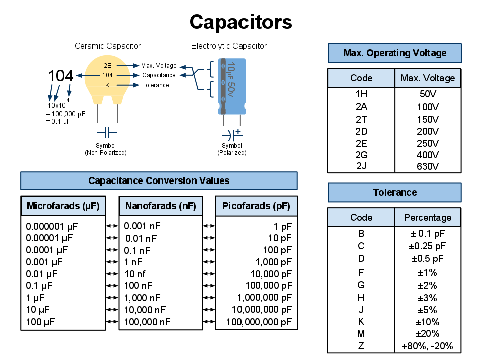
 Capacitance is measured in Farads (F). Farads are a bit of a weird measurement, in that 1 Farad is very big: most capacitors are a much smaller fraction of a Farad, and are typically measured in micro- (μ) or nano- (n) farads. The size of capacitor you use will matter a lot, so make sure you get the right one for your circuit. The chart below shows how to identify different types and values of capacitors.
 ## LEDs
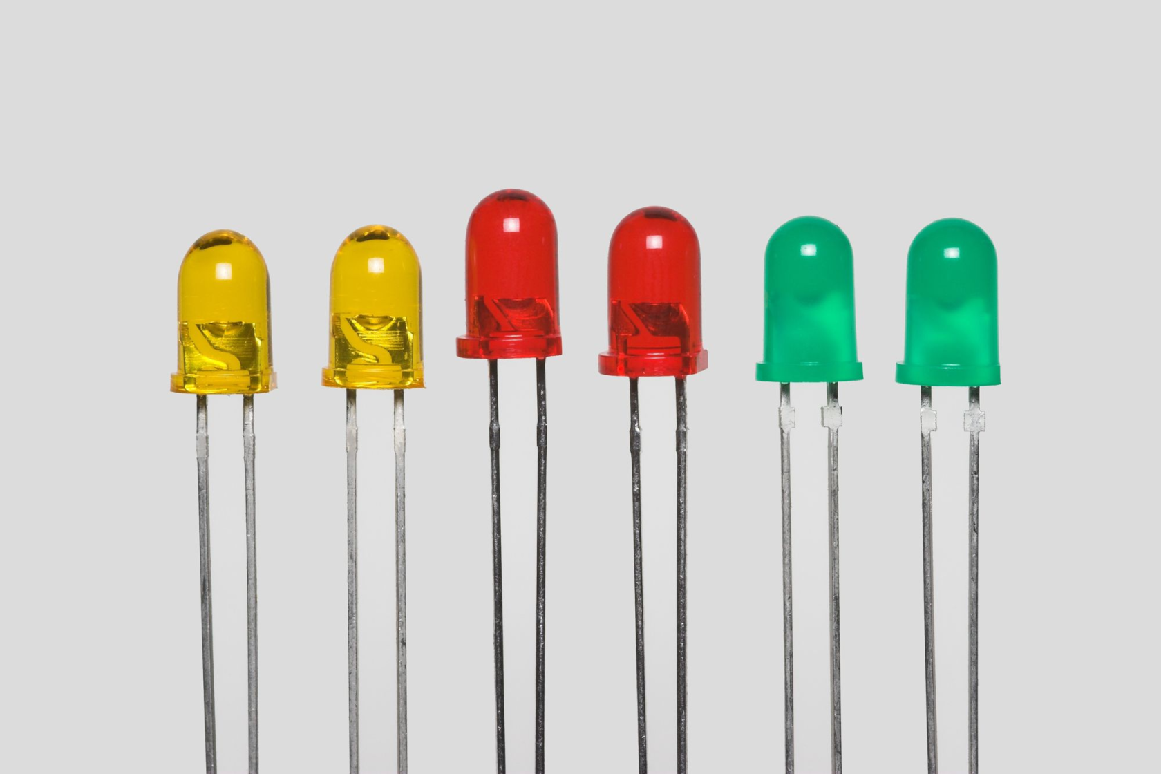
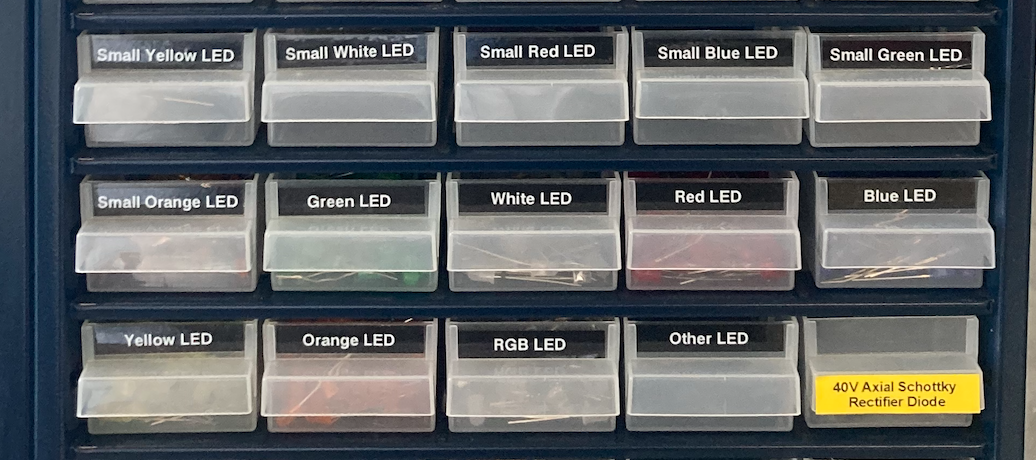 LED is short for 'light emitting diode' -- these are electronic components that emit light in circuits. All diodes are polar components, meaning that they will only work if they are placed the right way round. On an LED, the side that goes toward ground will normally be indicated by a shorter leg, and a flattened side to the casing. On a circuit diagram, the direction is indicated by an arrow, with the pointing side of the arrow pointing toward ground.
 In the CCI we have lots of different colours of LEDs. In general, they only require a small amount of current to work. If you put too much current through them, they will blow up! To avoid this, you can place them in series with a resistor, which will limit the flow of current. It's important to make this resistor not too large either, as if it's very big the LED won't get enough current to work. For a regular 5V circuit, a 220Ω resistor is normally about right.
 ## Diodes
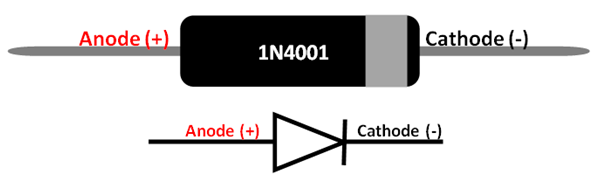
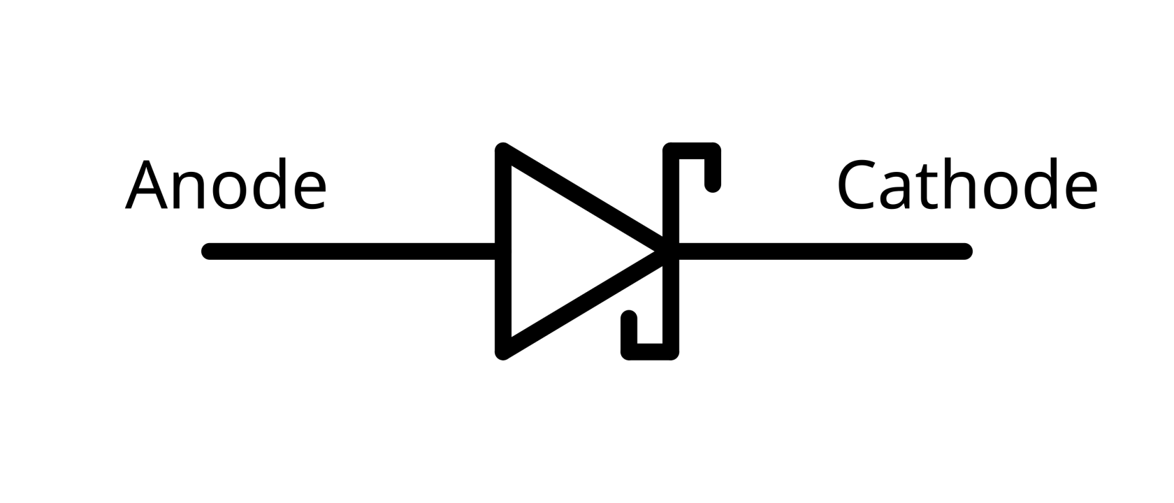
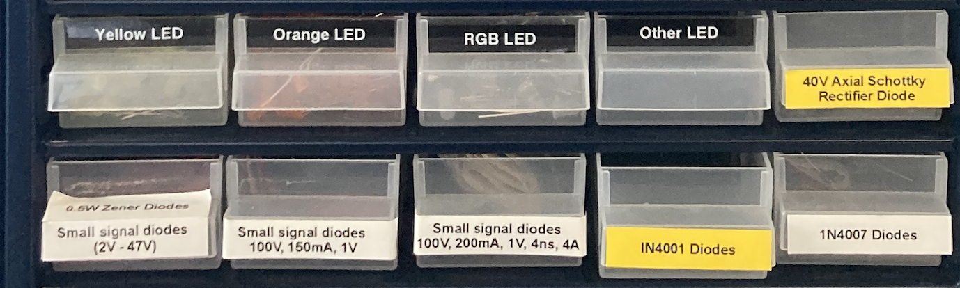 Diodes are components used to ensure that current only flows in one way. Often they're used in circuits with motors to protect more delicate components! There are a few different types available -- the IN4001 and IN4007 diodes are used for larger currents (around 1Amp), whereas the small-signal diodes are for circuits with a small amount of current (e.g. the amount that would come from an Arduino).
 We also have stock Schottky diodes -- these are used in rectifier circuits, where it really matters how quickly a diode changes direction. A rectifier circuit is used to switch from AC to DC current. Schottky diodes have a different electrical signal.
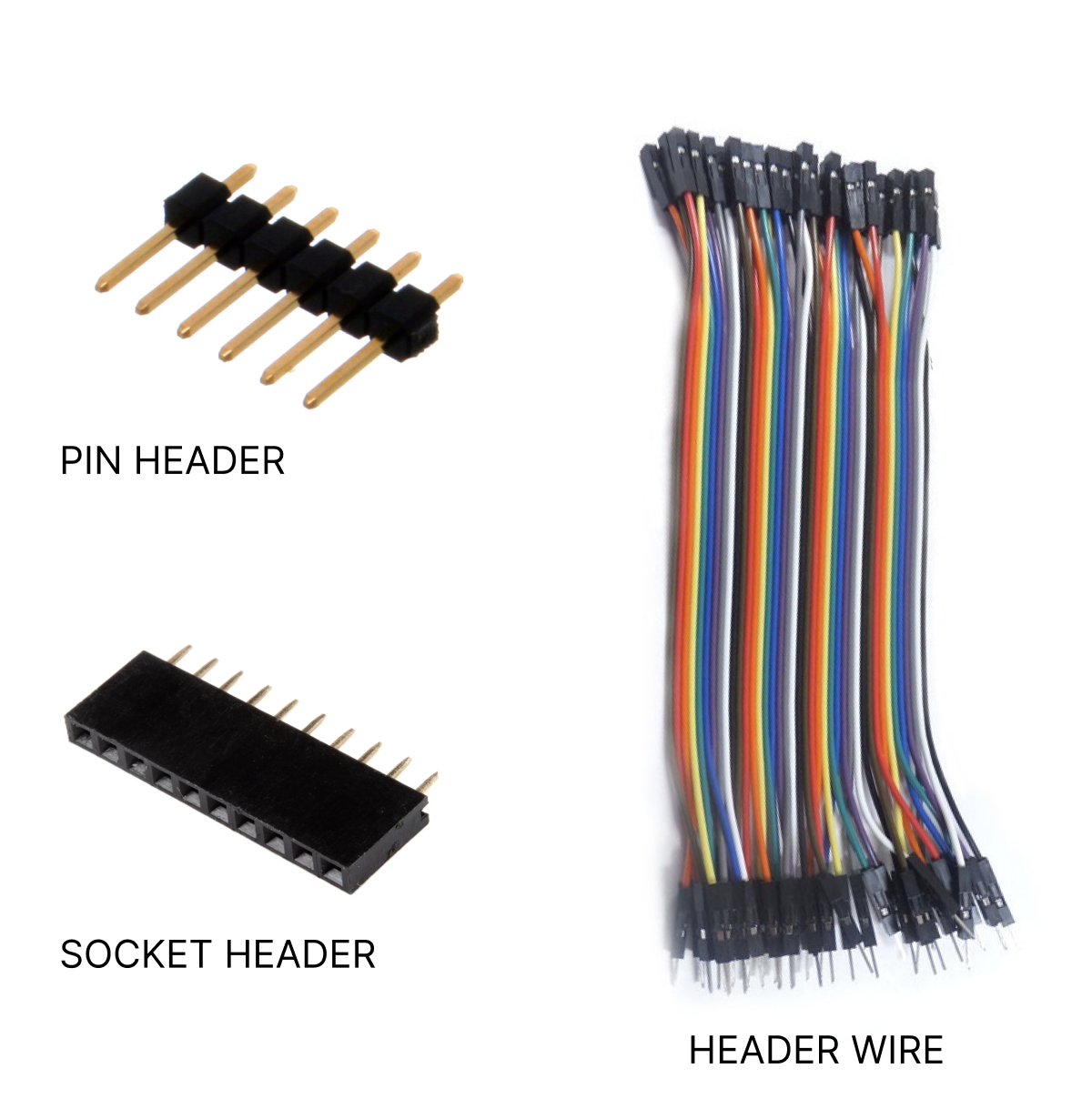
 ## Connectors
Making good connections is a core part of constructing robust circuits. In the CCI we stock some wires that come with connectors already built in (the 'header wires' that are given out in Arduino kits). If you are soldering a board which uses these kinds of wires, we have headers and sockets available in the spinner that these will correspond to. The technical name for these is 'dupont connectors'. You can use snips to cut the pins and sockets to the number you require.
## Connectors
Making good connections is a core part of constructing robust circuits. In the CCI we stock some wires that come with connectors already built in (the 'header wires' that are given out in Arduino kits). If you are soldering a board which uses these kinds of wires, we have headers and sockets available in the spinner that these will correspond to. The technical name for these is 'dupont connectors'. You can use snips to cut the pins and sockets to the number you require.
 For making more robust connections, we also stock:
* JST Connectors
* Screw Terminals
* Crimp Terminals
There's a much longer guide to these kinds of connectors in the [Electronics Fabrication guide](https://wiki.cci.arts.ac.uk/books/physical-computing-lab/page/electronics-fabrication-tips-tools-and-resources#bkmrk-connectors).
## e-Textiles
For making more robust connections, we also stock:
* JST Connectors
* Screw Terminals
* Crimp Terminals
There's a much longer guide to these kinds of connectors in the [Electronics Fabrication guide](https://wiki.cci.arts.ac.uk/books/physical-computing-lab/page/electronics-fabrication-tips-tools-and-resources#bkmrk-connectors).
## e-Textiles
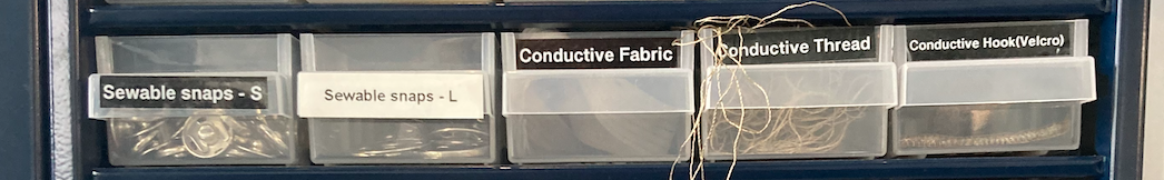 We stock some basic e-Textiles equipment in the spinner, and have more on request. These components are more limited, so only take what you need. They include:
* conductive thread and fabric
* sewable snaps
* sewable LEDs
* battery holders
* flexible silicone wire
For more info on e-textiles equipment and provision at the CCI, take a look at [this guide](https://wiki.cci.arts.ac.uk/books/etextiles-lab/page/digital-and-e-textile-design-at-the-cci).
## Advanced Components
We keep a number of components that are useful in more complex circuits. These might include circuits that don't use an Arduino, for example, oscillators, synthesisers, amplifier and radio circuits. If you're curious about any of these you can ask a technician for help, but you're also welcome to test out using components that appear in circuit diagrams.
We stock some basic e-Textiles equipment in the spinner, and have more on request. These components are more limited, so only take what you need. They include:
* conductive thread and fabric
* sewable snaps
* sewable LEDs
* battery holders
* flexible silicone wire
For more info on e-textiles equipment and provision at the CCI, take a look at [this guide](https://wiki.cci.arts.ac.uk/books/etextiles-lab/page/digital-and-e-textile-design-at-the-cci).
## Advanced Components
We keep a number of components that are useful in more complex circuits. These might include circuits that don't use an Arduino, for example, oscillators, synthesisers, amplifier and radio circuits. If you're curious about any of these you can ask a technician for help, but you're also welcome to test out using components that appear in circuit diagrams.
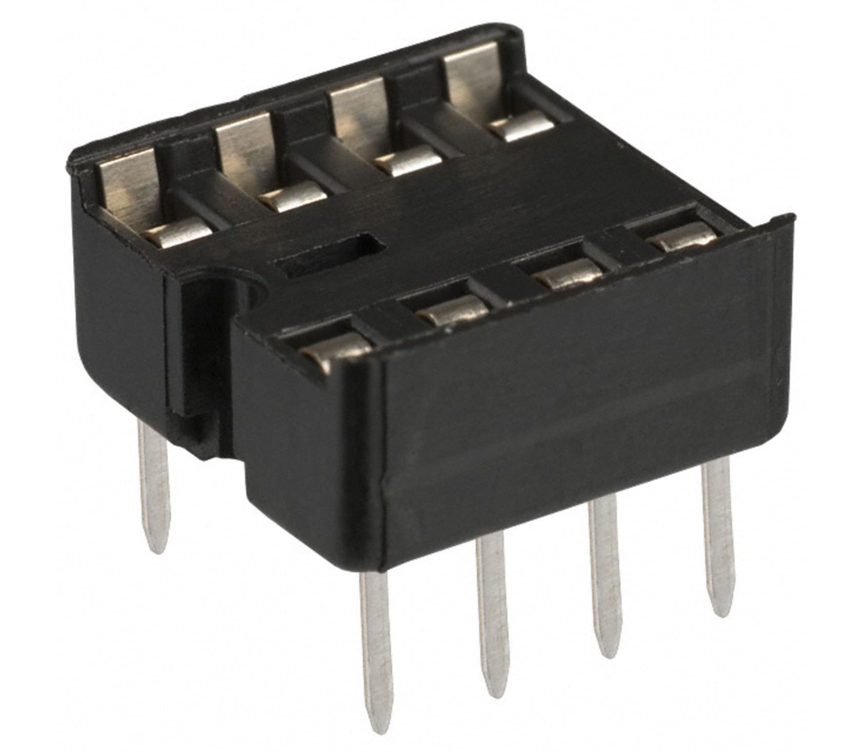
 Many of these components are packaged as IC's, or Integrated Circuits -- small rectangles with 8 or more legs. When soldering these into stripboards, it's worth using a DIP socket to hold them rather than soldering the chip directly in -- if anything goes wrong, it's much easier to change it out. Most ICs will have the chip number etched on top, and 'pin 1' of the IC will be marked with a dot or a notch. More information on ICs is available [here](https://learn.sparkfun.com/tutorials/integrated-circuits/all).
 With some of these components, we only stock a small number of these as they're typically not used in student projects -- if you plan to use many of something, please ask us first!
### Op-Amps
Op-amps (operational amplifiers) are used to amplify signals in circuits. These require a dual power supply to work -- one with a positive and negative voltage. For lower amplification applications this can be achieved using a simple circuit to make a +-4.5V power supply from a 9V input.
With some of these components, we only stock a small number of these as they're typically not used in student projects -- if you plan to use many of something, please ask us first!
### Op-Amps
Op-amps (operational amplifiers) are used to amplify signals in circuits. These require a dual power supply to work -- one with a positive and negative voltage. For lower amplification applications this can be achieved using a simple circuit to make a +-4.5V power supply from a 9V input.
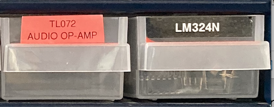 * TL072 -- this is an audio op-amp with a high quality signal
* LM324N -- this is a high voltage gain op-amp
### Shift Registers
### 555 Timers
### CMOS logic
### Inductors
### Schmitt Triggers
These are used to remove noise, and can also be used as an oscillator (e.g. in making sounds). We have these available in the [SN74HC14N](https://uk.rs-online.com/web/p/inverters-ics/0442943?gb=s) package, which contains 6 schmitt triggers.
### Microcontrollers
We stock small numbers of STM32 and ATMEGA chips. The latter of these are the chips used in arduino boards, and can be programmed using the IDE. This allows you to fabricate your own boards from scratch, which can be useful for miniaturised circuits e.g. for wearables. The STM chips were used in the synth-building workshop run by [Dirty Electronics](https://www.dirtyelectronics.org/) last year.
* TL072 -- this is an audio op-amp with a high quality signal
* LM324N -- this is a high voltage gain op-amp
### Shift Registers
### 555 Timers
### CMOS logic
### Inductors
### Schmitt Triggers
These are used to remove noise, and can also be used as an oscillator (e.g. in making sounds). We have these available in the [SN74HC14N](https://uk.rs-online.com/web/p/inverters-ics/0442943?gb=s) package, which contains 6 schmitt triggers.
### Microcontrollers
We stock small numbers of STM32 and ATMEGA chips. The latter of these are the chips used in arduino boards, and can be programmed using the IDE. This allows you to fabricate your own boards from scratch, which can be useful for miniaturised circuits e.g. for wearables. The STM chips were used in the synth-building workshop run by [Dirty Electronics](https://www.dirtyelectronics.org/) last year.