Robotics Lab
- About the Robotics Lab
- Lab Rules
- Robots and components we have
- How To Guides
- Using Dobot Magician V2
- Using UR5e with 2F-85 adaptive gripper
- Using QTrobot
- Using Turtlebot4
- Using Pololu 3pi+ 32U4 OLED Robot
- Using Go1 Edu robot dog by Unitree
- Using NAO V6
- Using mBot2 by makeblock education
- Soft Robotics
About the Robotics Lab

The Robotics Lab is located on the Ground floor of Greencoat Building, in GB_G11.
Opening Hours
| Open | Staffed | |
|---|---|---|
| Weekday | 09:30–16:30 | 09:00–17:00 |
| Weekend | Closed | Closed |
Staff
 |
| Rohit Ramesh Thampy |
| he/him |
Lab Rules
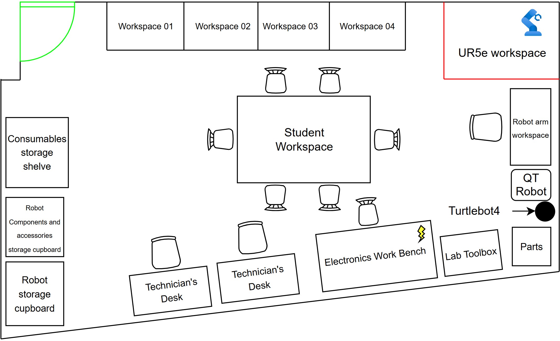
Lab Layout
Lab Rules
- The lab is open from 9:30 - 12:30 and 13:30 - 16:30, Monday to Friday.
- If you are looking to use any robotics equipment, it must be booked at least a day in advance. Bookings can be made via ORB.
- The robots and equipment in the lab are for indoor use only, therefore do not use them outdoors.
- The UR5e and the Go1 requires an induction before you use it for the first time. If you are looking to use any of them and it is your first time, then you can book an induction for them through ORB.
- The tools from the lab toolbox should only be used within the lab and then returned. If you need to use some tools outside the lab, then a basic toolbox set is present within the consumables storage shelf in the lab.
- No food or drinks are allowed while working with the UR5e or the electronics workbench; however, you can have bottled water.
- If you are unsure about conducting your work in the lab or have any questions, please contact Rohit Ramesh Thampy on Slack or Outlook.
- Please remember to tidy up the equipment and your work area once you are finished or by the end of the day. Keeping the lab clean ensures a safe and pleasant environment for everyone.
Robots and components we have
Robots
| Item | Quantity | Image |
|---|---|---|
| Universal Robot UR5e | 1 |  |
| Dobot Magician V2 | 2 |  |
| QTrobot | 1 |  |
| Go1 Edu | 1 |  |
| Turtlebot4 | 1 |  |
| Pololu 3pi+ 32U4 OLED Robot | 4 |  |
| mBot2 | 1 |  |
Components
| Item | Quantity | Image |
|---|---|---|
| Dynamixel Starter Kit | 7 |  |
| Dynamixel AX-12A servos | 14 |  |
| Dynamixel AX-12W servos | 2 |  |
How To Guides
Using Dobot Magician V2
What is it?
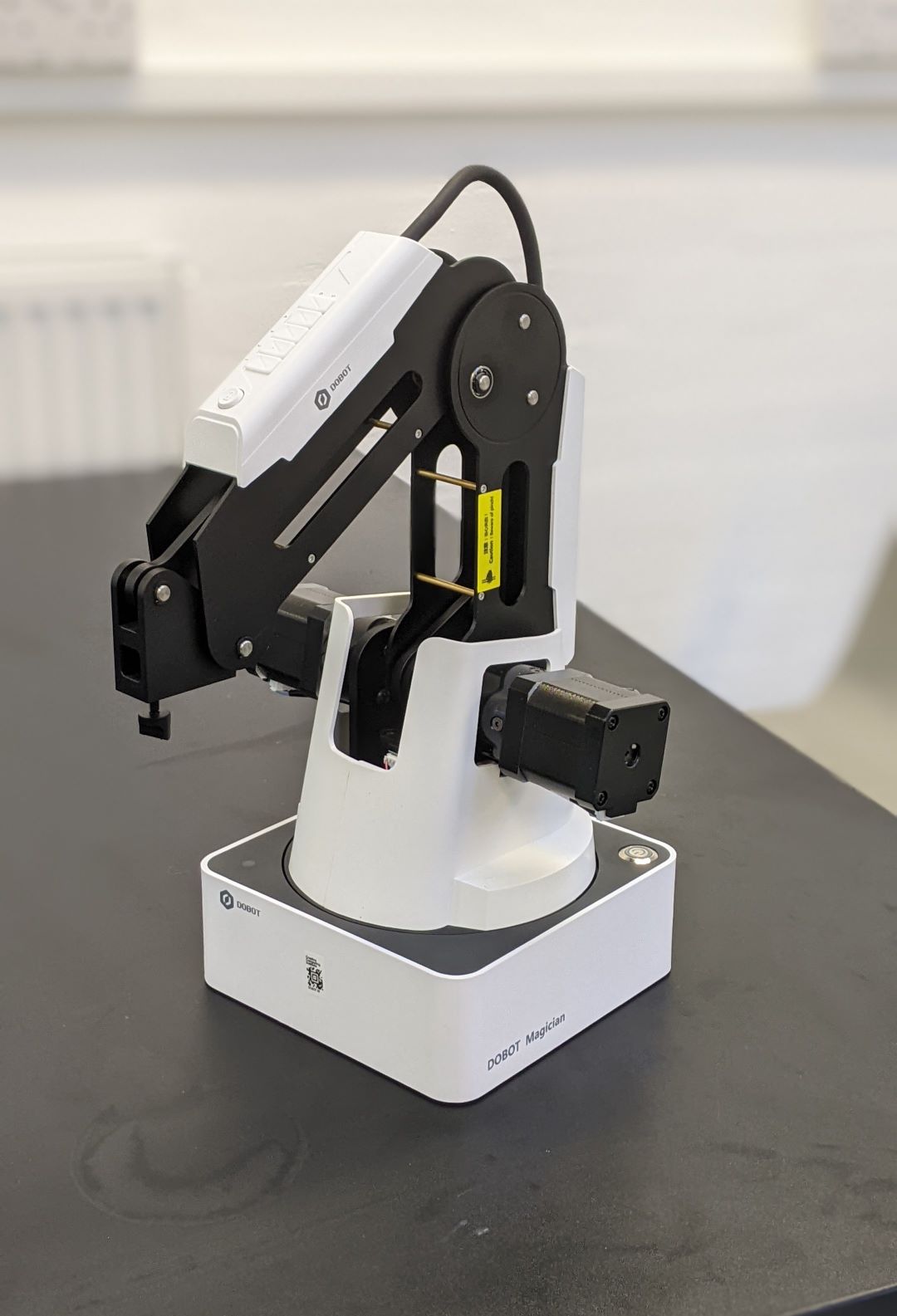
The Dobot magician is a 4 Degree of Freedom robotic arm.
What can it do?
Some use cases of the Dobot Magician consist of:
- Drawing of writing using its pen end-effecotr.
- Pick and place using its suction or fingered gripper.
- Basic 3D printing with a 3D printer nozzle end-effector add on and a prusa slicer.
Dobot magician basic setup
What you will need
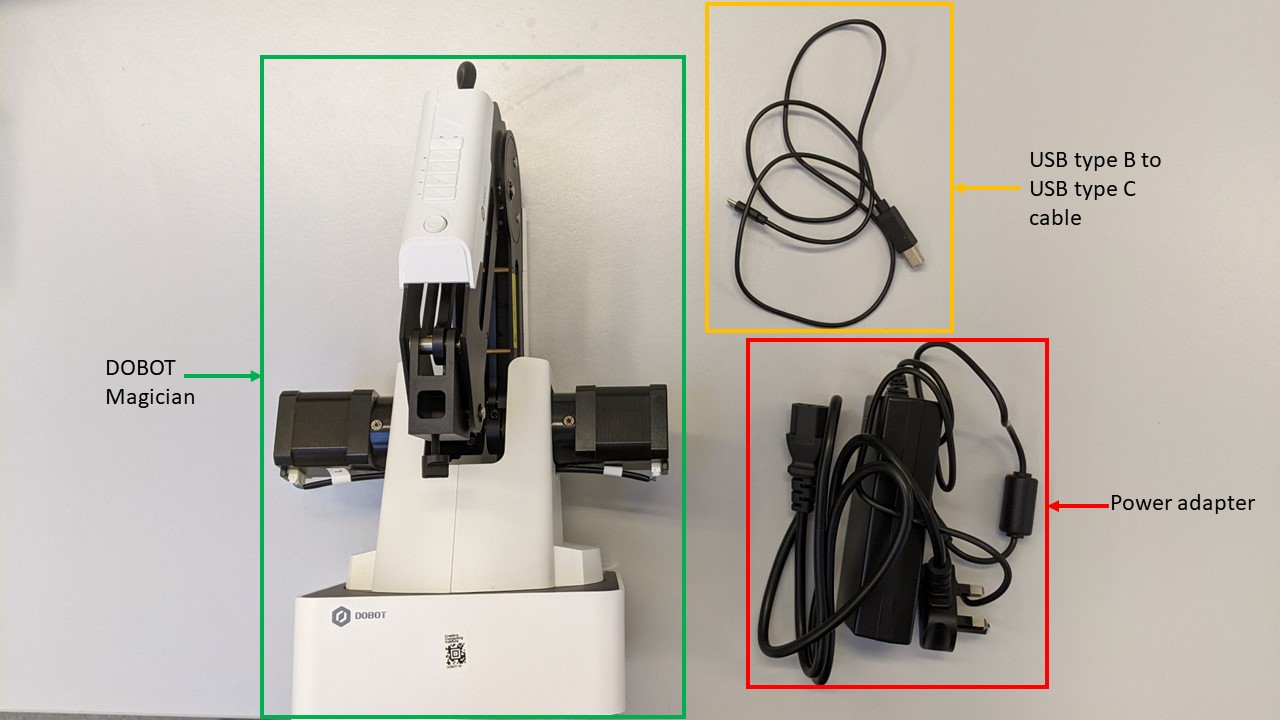
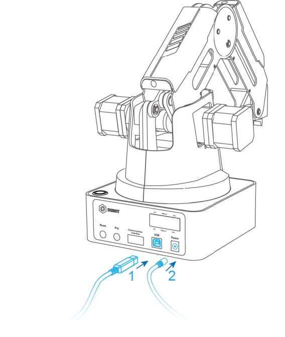
The setup
Note: Ensure that there are no obstruction around the robot.
- Connect the Dobot Magician to your computer with the supplied USB cable.
- Connect the DObot Magician to a power source with the supplied power adapter.
Powering on/off Dobot Magician
Power on
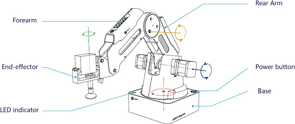
Before powering on the Dobot Magician, align it into its neutral position as seen in the image below and then press down on the power button that is located on the base of the robot.
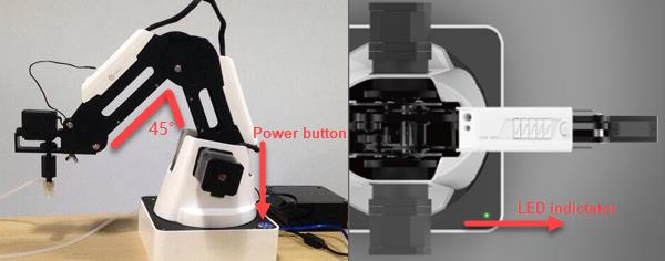
Once the robot is powered on, the LED indicator turns yellow, and all stepper motors lock. After about 7 seconds, the robot will play a short "beep" sound and the LED indicator will turn green. Now the Dobot Magician have completed its power on sequence.
Note: If the LED indicator is red after the robot is powered on, this means that the robot arm has reached one or many of its axis limits. To get it back working,just press and hold the unlock button  located on the forearm of the robot and move it to a desired position.
Power off
When the LED indicator is green, press down the power button to turn off the robotic arm. In this case, the forearm moves slowly to the rear arm and stops. Then it has completed the power off sequence.
How to control Dobot Magician?
There are two ways of controlling the Dobot magician.
- Using DobotLab
- Using python
Note: Any software or documentation for the Dobot magician can be found within the download center of Dobot's website but in order to download anything from there, you will need to create an account with them.
DobotLab
DoboLab is a web based interface that is used to teach, learn and work with the Dobot magician and some other Dobot products.
To use it , you can click here or just search for "DobotLab" on your favorite browser. It should look something like the image below.
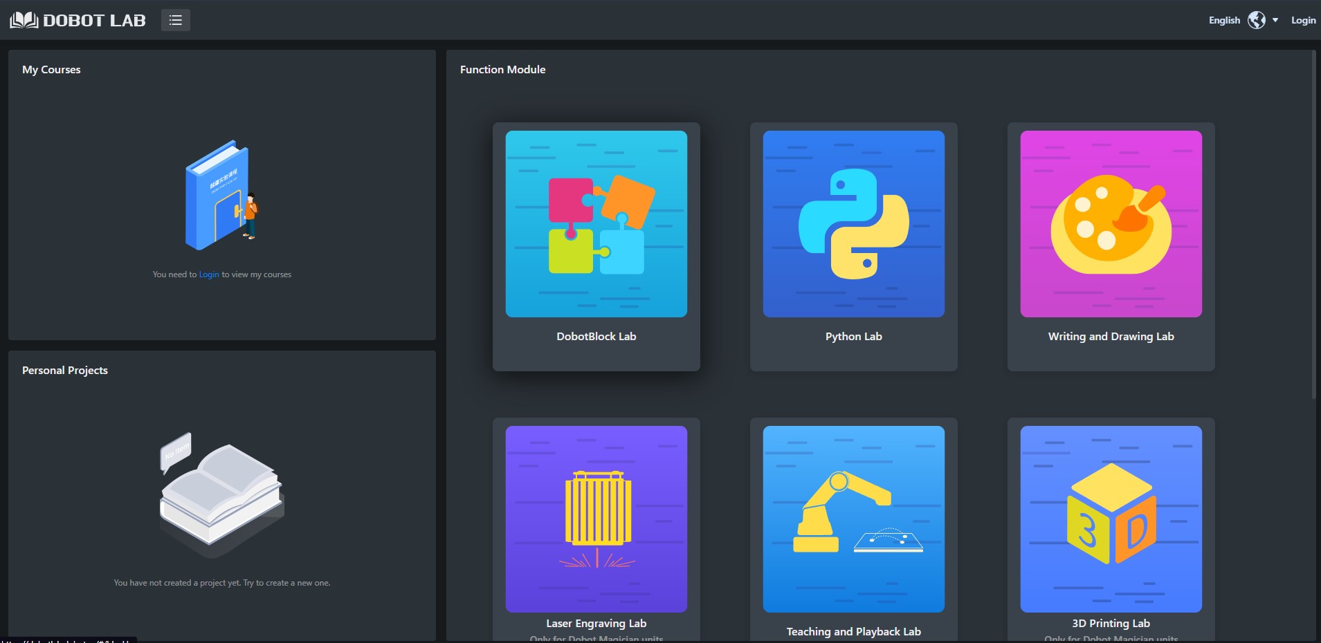
You can register with DobotLab if you would like to save any progress but this is completely optional.
On the DobotLab page, choose any of the application tiles to work with. But once you have chosen an application tile, you will get a pop up stating "DobotLink is not started" and you will also have the option to download and install DobotLink.

DobotLink is the piece of software that has the drivers for controlling the Dobot Magician and acts as a bridge between the DobotLab and the Dobot Magician. Make sure you download and install this, as without it you will not be able to control the robot using DobotLab.
If you have previously downloaded DobotLink, click on "Start" if not download and install it and then click "Start".
If everything goes well, the pop will say "DobotLink started successfully" as shown below.
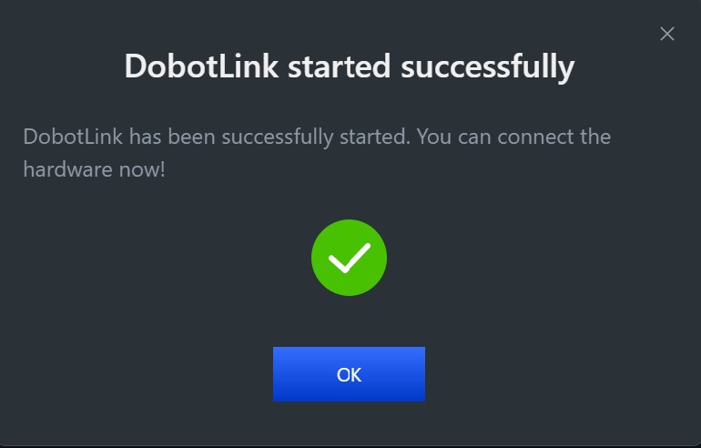
Click "Ok" and it will continue to the chosen application.
On the application page, on the top right of the screen you should see the following.
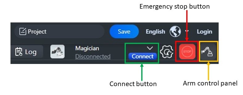
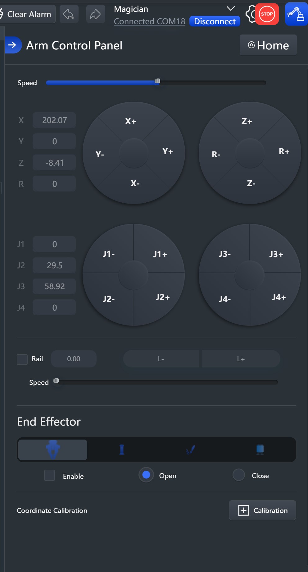
Here, if you click on "connect", it should connect you to the robot and if you then click on the "arm control panel", a control panel such as the one given below should appear which will allow you to control the Dobot Magician.
Feel free to play around with the other application as well and if you need any more details, have a look at the user manual which can be found within Dobot's download center . The document you will need to search for is Dobot Magician V2 User Guide (DobotLab-based).
Using python to control Dobot Magician
There are two options for controlling the Dobot magician using python.
None of these options have undergone extensive testing, use it at your own risk.
-
dobot-python by Alex Gustafsson (Recommended as it uses the newer communication protocol v1.1.5)- click here
-
pydobot, a python library for Dobot Magician by Luis Mesas - click here
Troubleshooting
- Serial not found error - You might get the serial not found error, it means that you don't have pyserial installed, to install it use the command
pip install pyserialorpython3 -m pip install pyserial.
Frequently asked questions
-
The LED on the robot has turned amber instead of green, what should I do?
If the LED on the robot has turned amber during start up, that means the robot is in a restricted area. You will need to manually move it back to its safe operating space.
To do this, simply press the circular button which has a logo of an unlocked lock that is located on the forearm of the robot. While holding the button, move the arm of the robot out of the restricted area.
Using UR5e with 2F-85 adaptive gripper
Safety guidelines
Important: This robot requires an induction before you use it for the first time. If you have not completed this induction, please contact Rohit Ramesh Thampy on Slack.
- Please remove any loose jewellery or clothing before working with this robot.
- If you have long hair, please secure it using a hair tie.
- Do not place your hands or fingers on the joints of the robot or in between the robotiq gripper.
- When testing your program, switch the robot into reduced mode and decrease your speed to 50% and run it. If the robot is running without any collisions, increase the speed by 10%. Repeat this process till you reach 80% speed without any collisions. Once you have reached 80% you can switch the robot back to Normal mode and run it at 90% and 100% speed.
- If you make any significant changes to your robot program, such as adding a new waypoint, move command, velocity or acceleration change, follow
4.. - When a robot program is running, ensure that you are outside region marked with red tape.
What is it?
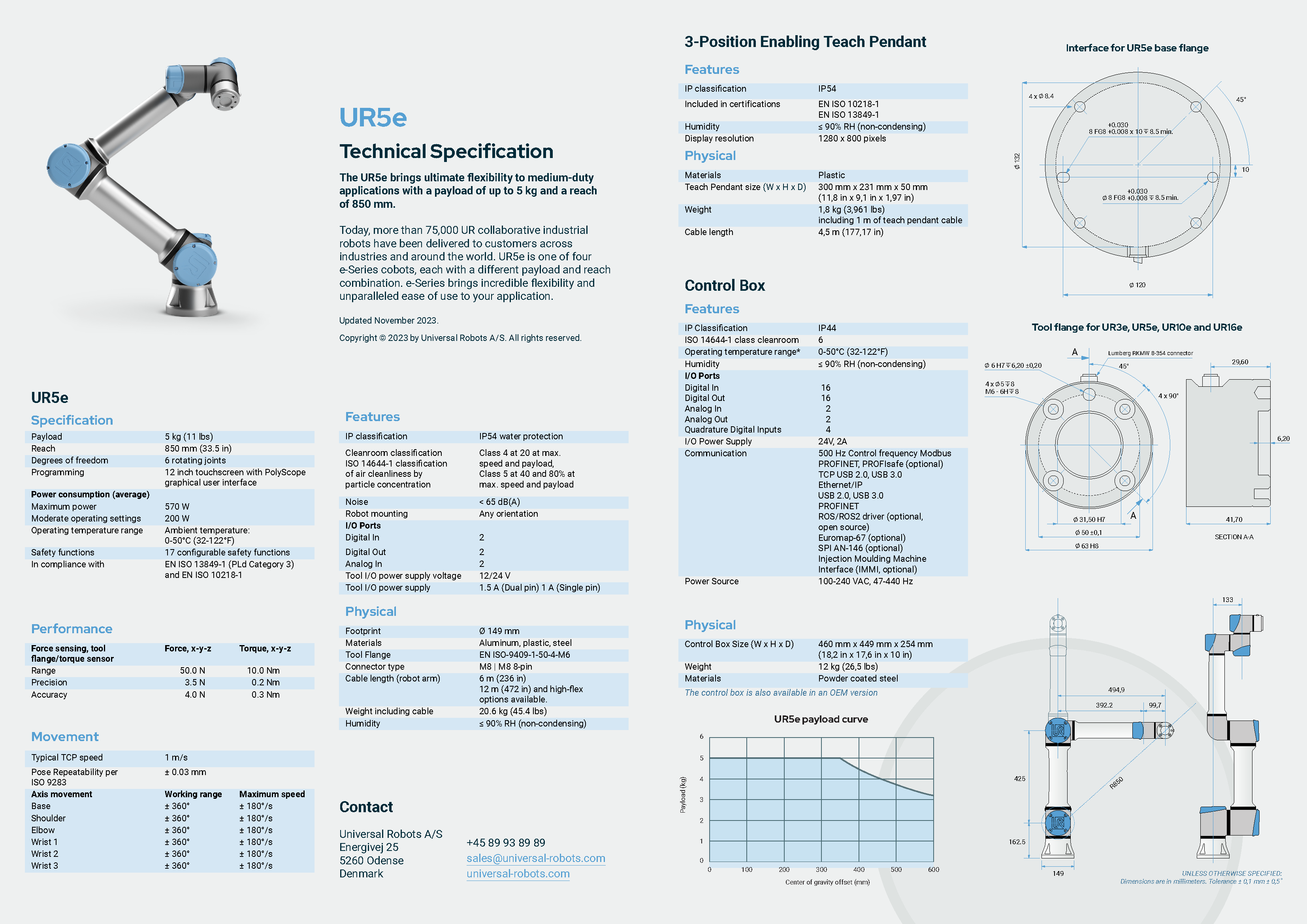
UR5e
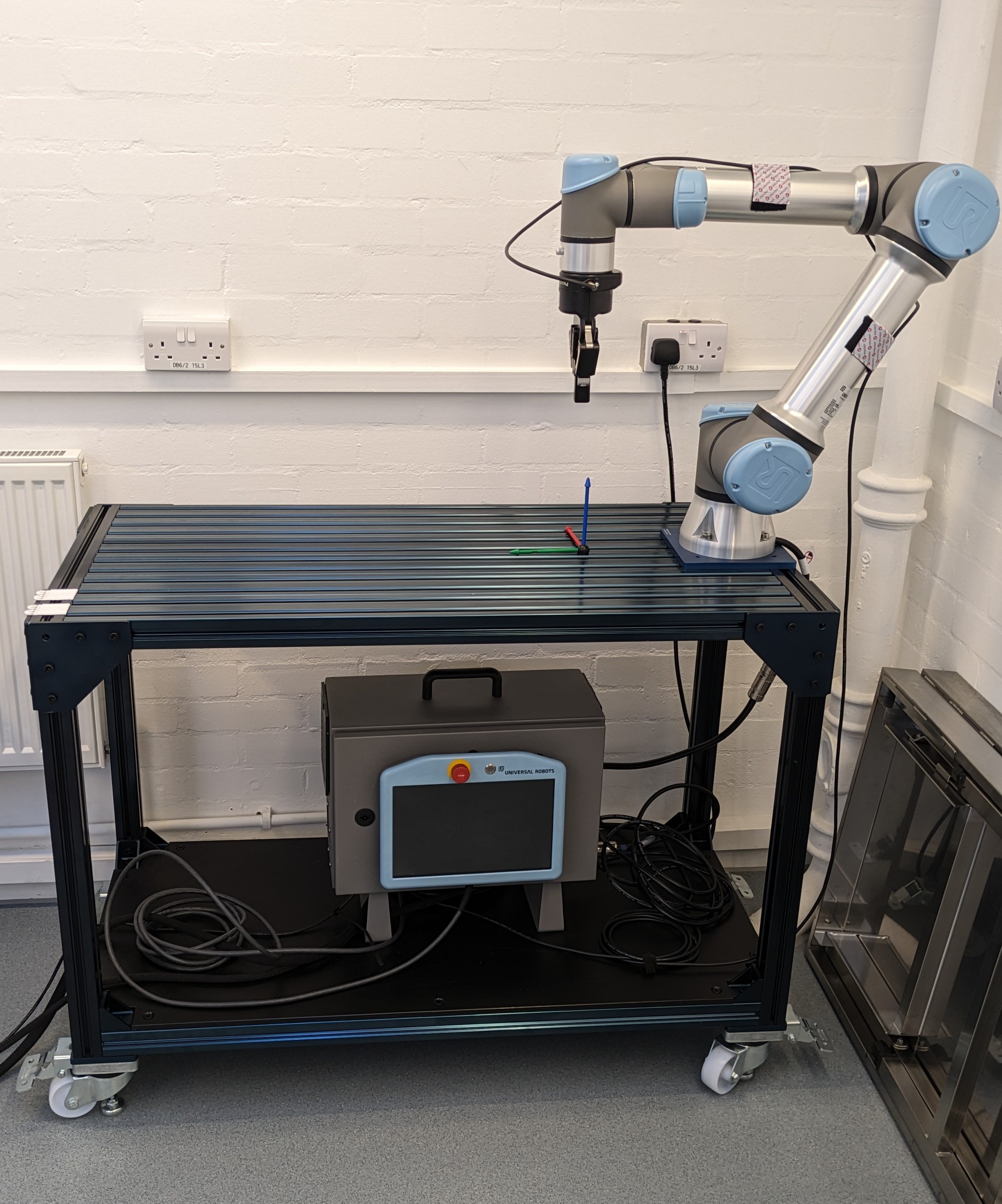
The UR5e by Universal Robots is a 6 Degree of freedom robotic arm. It is the gold standard for collaborative robots in the industry as it is designed to work alongside humans.
Robotiq 2F-85 adaptive gripper
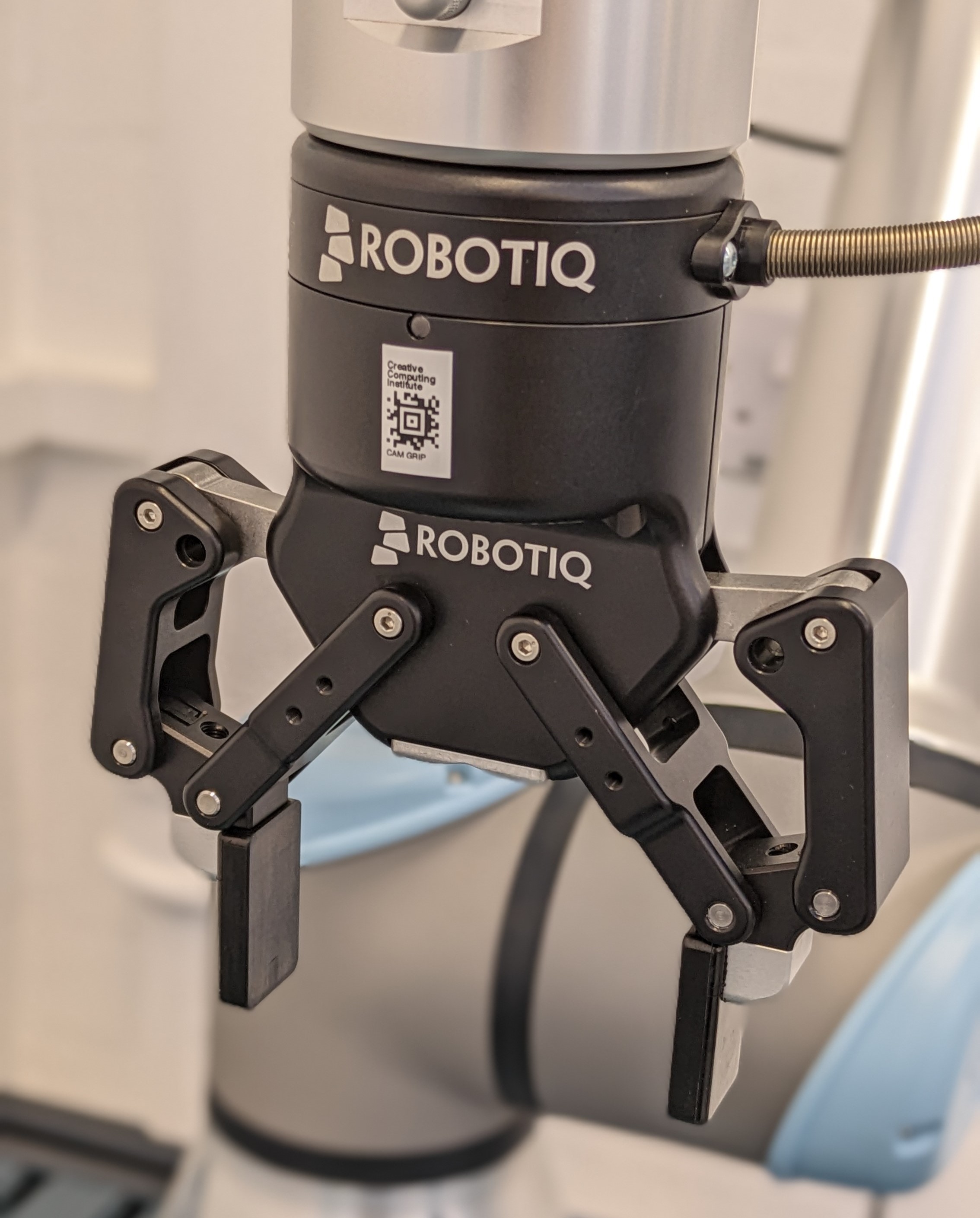
The 2F-85 adaptive gripper by Robotiq is an end-effector that is commonly used with robotic arms such as the UR5e. But the 2F-85 that we have at the robotics lab is rather special as it comes with a camera module as well.
What can it do?
The UR5e on its own is not of much use as it is a robotics platform and we as the user need to define an application to make it useful.
For example, since we have the 2F-85 gripper attached and setup on the robot arm we can now program it to carry on applications such moving objects around the workspace of the robot or carry out a repetitive process such as pick and place.
If you'd like, you can also design and attach your own end-effector to the robot which could give it a new capability!
The bottom line is, if you need to do something which requires repeatability, precision and accuracy, this robot might be able to to help you out.
Getting started
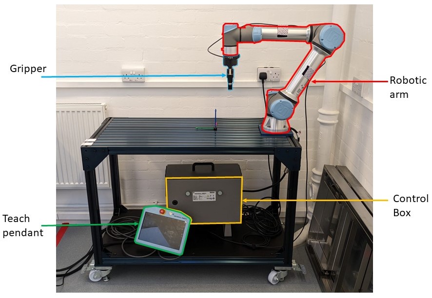
Core components of the UR5e
- The robotic arm
- The control box
- The teach pendant
- The gripper
Power on/off
Power on
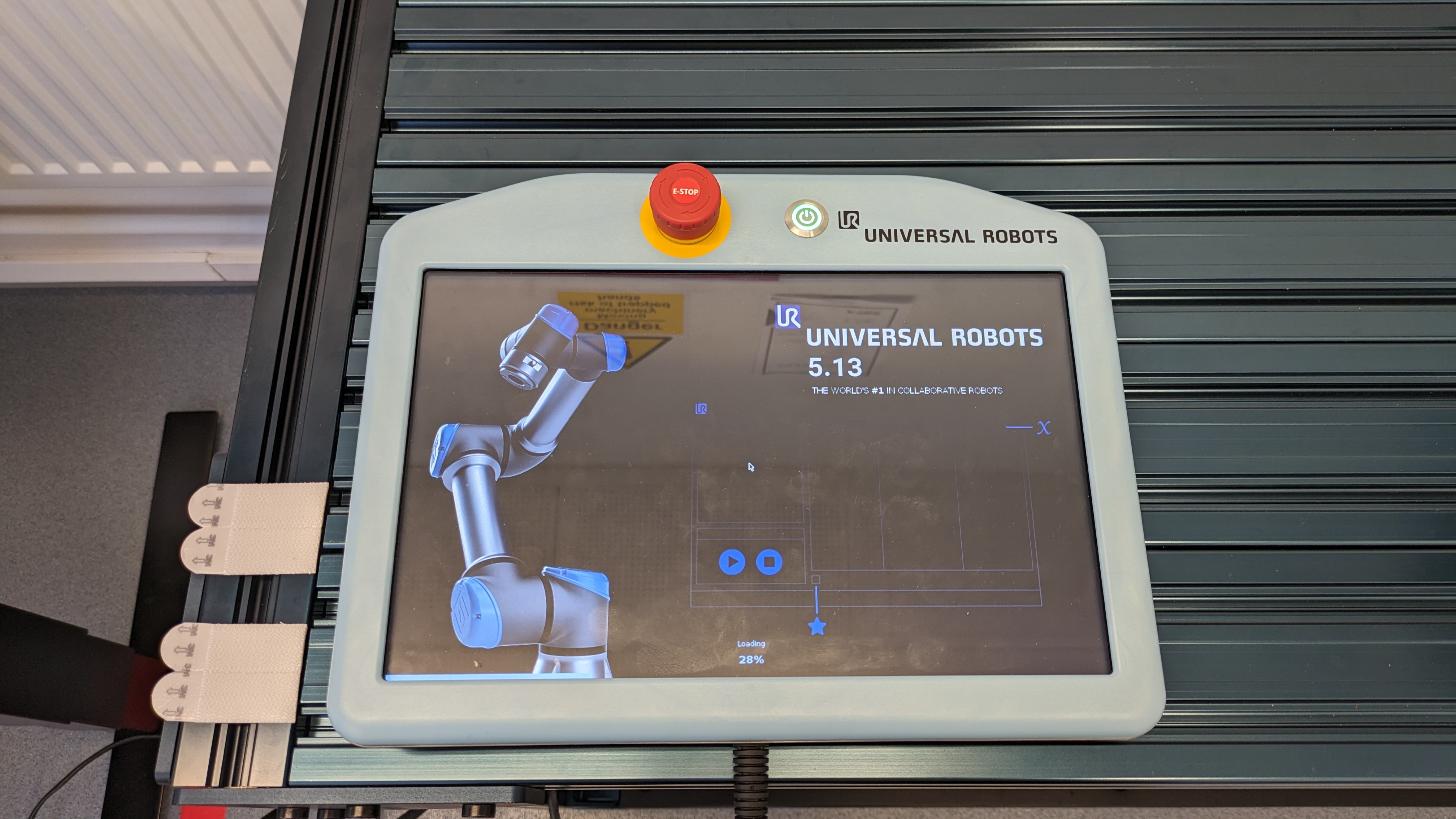
- To power on the robot press down on the power button located at the top of the teach pendant. You will notice that the LED within the power button turns green and after a couple of seconds you will see the Universal Robots logo as shown below.
![]()
- The screen will then change to a loading screen as shown below and it will take a couple of minutes to load completely.
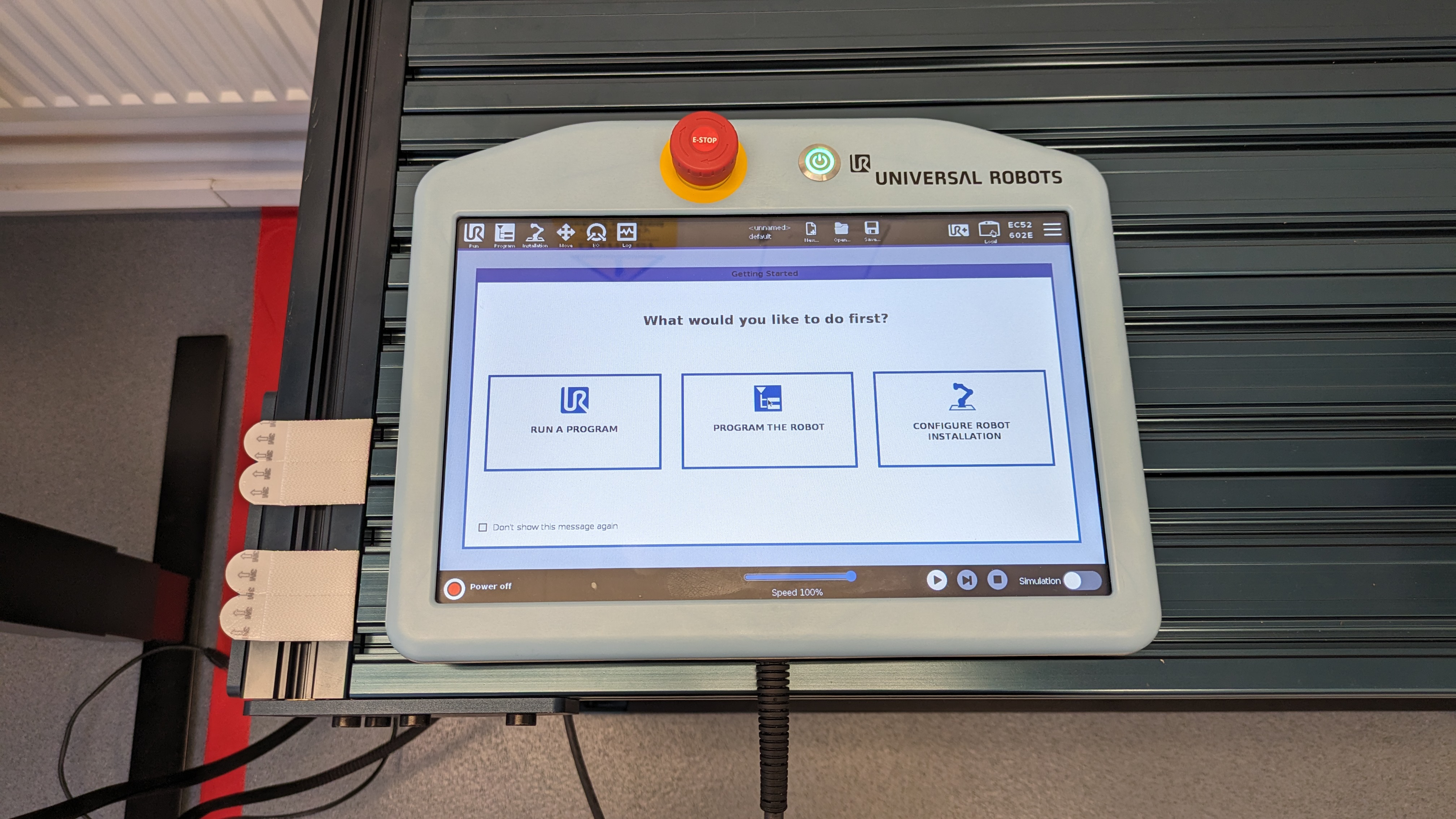
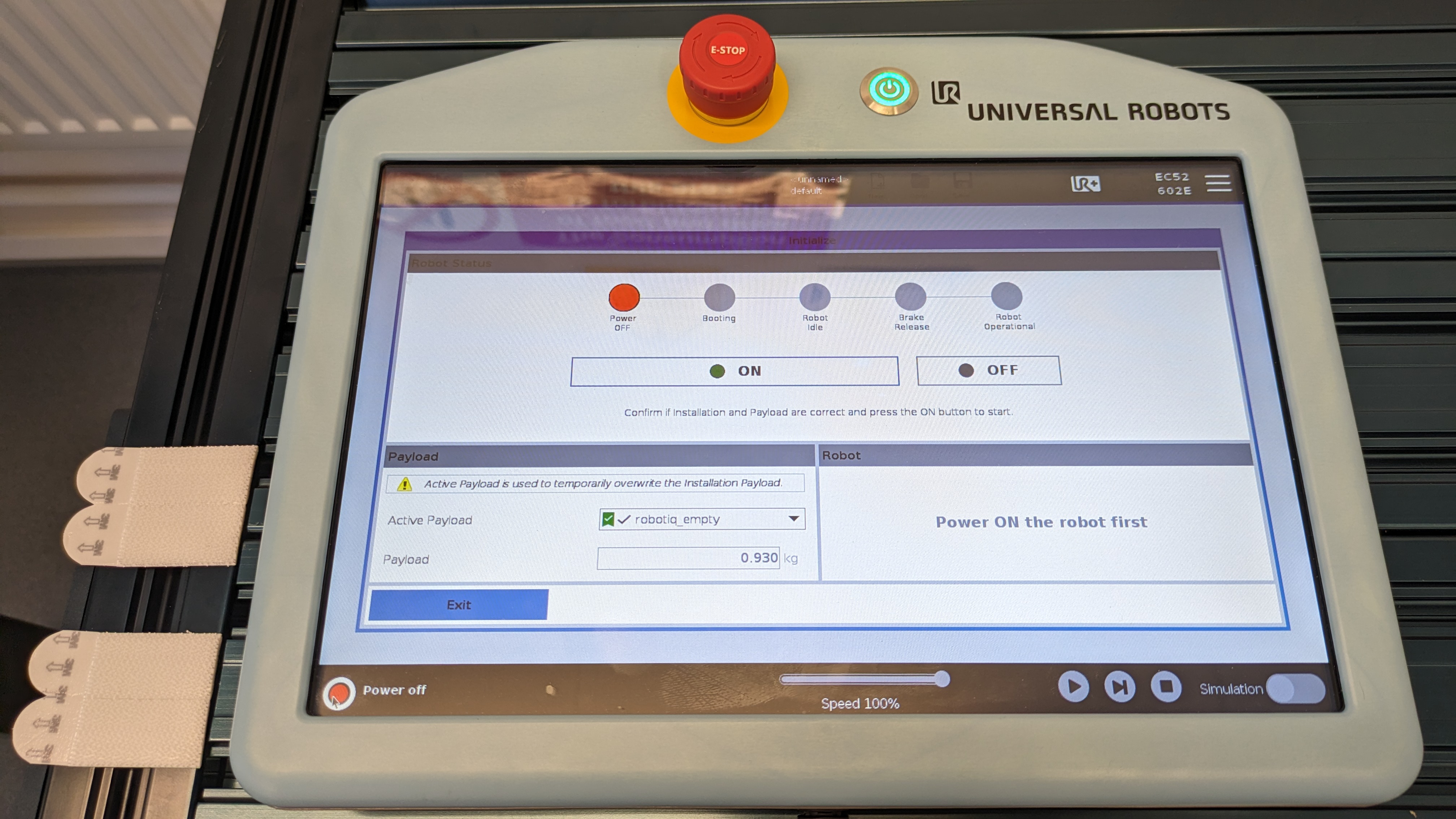
- Once the loading in complete you will see a getting started screen as shown below. At this stage only the control box has booted up but robot arm itself is not powered on.
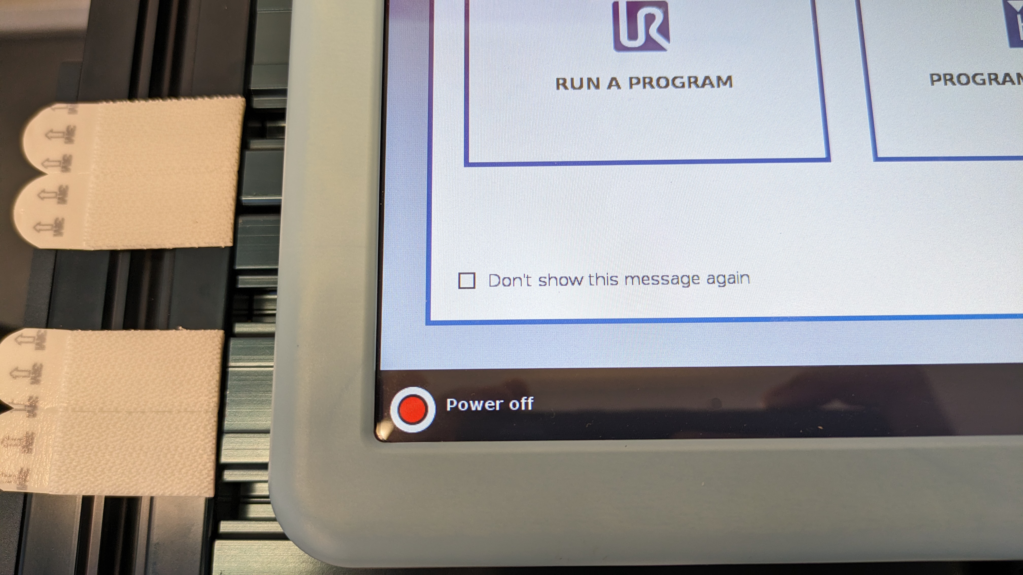
- To power on the robot arm, click on the red button that is located at the bottom left corner of the screen.
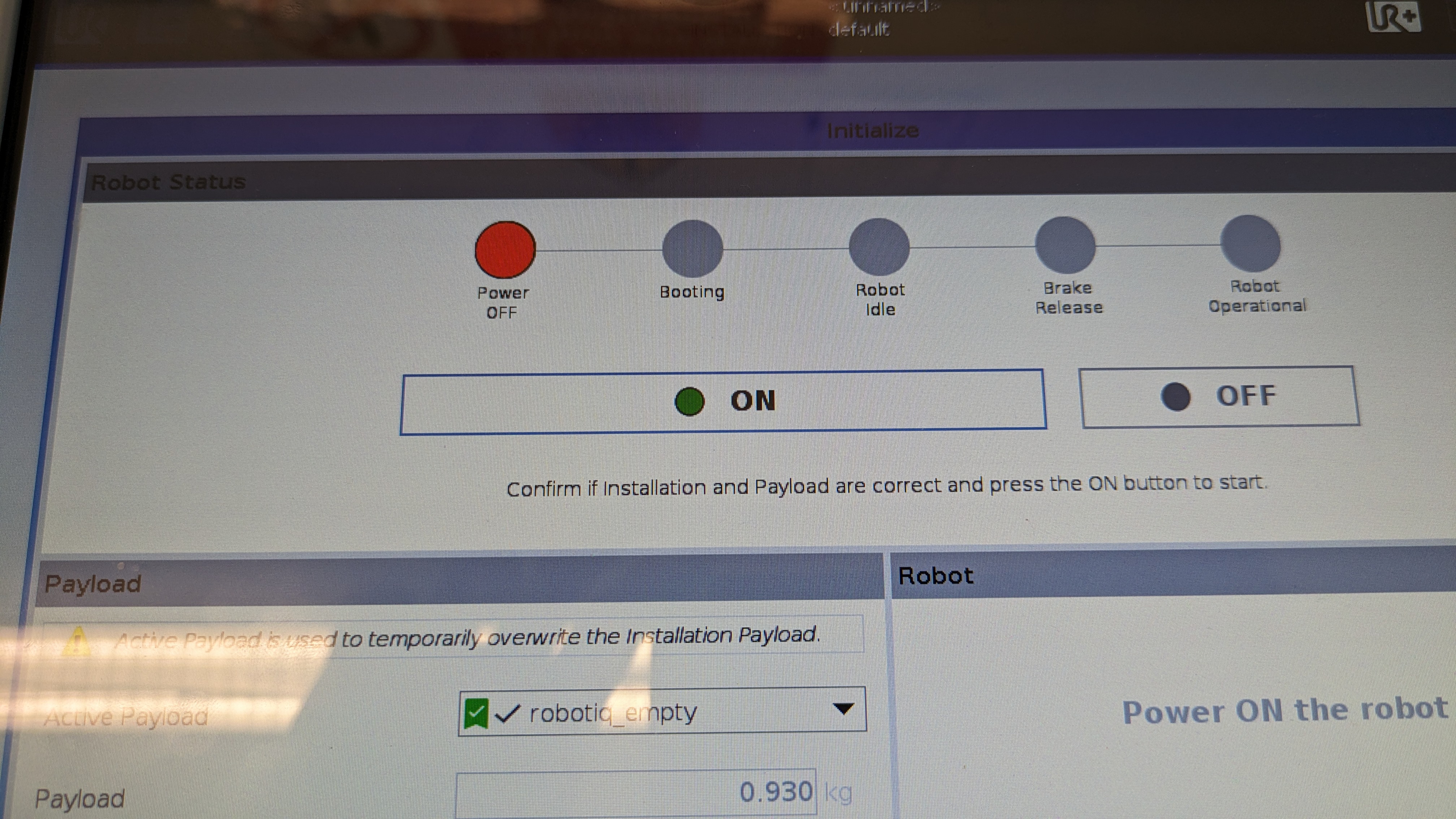
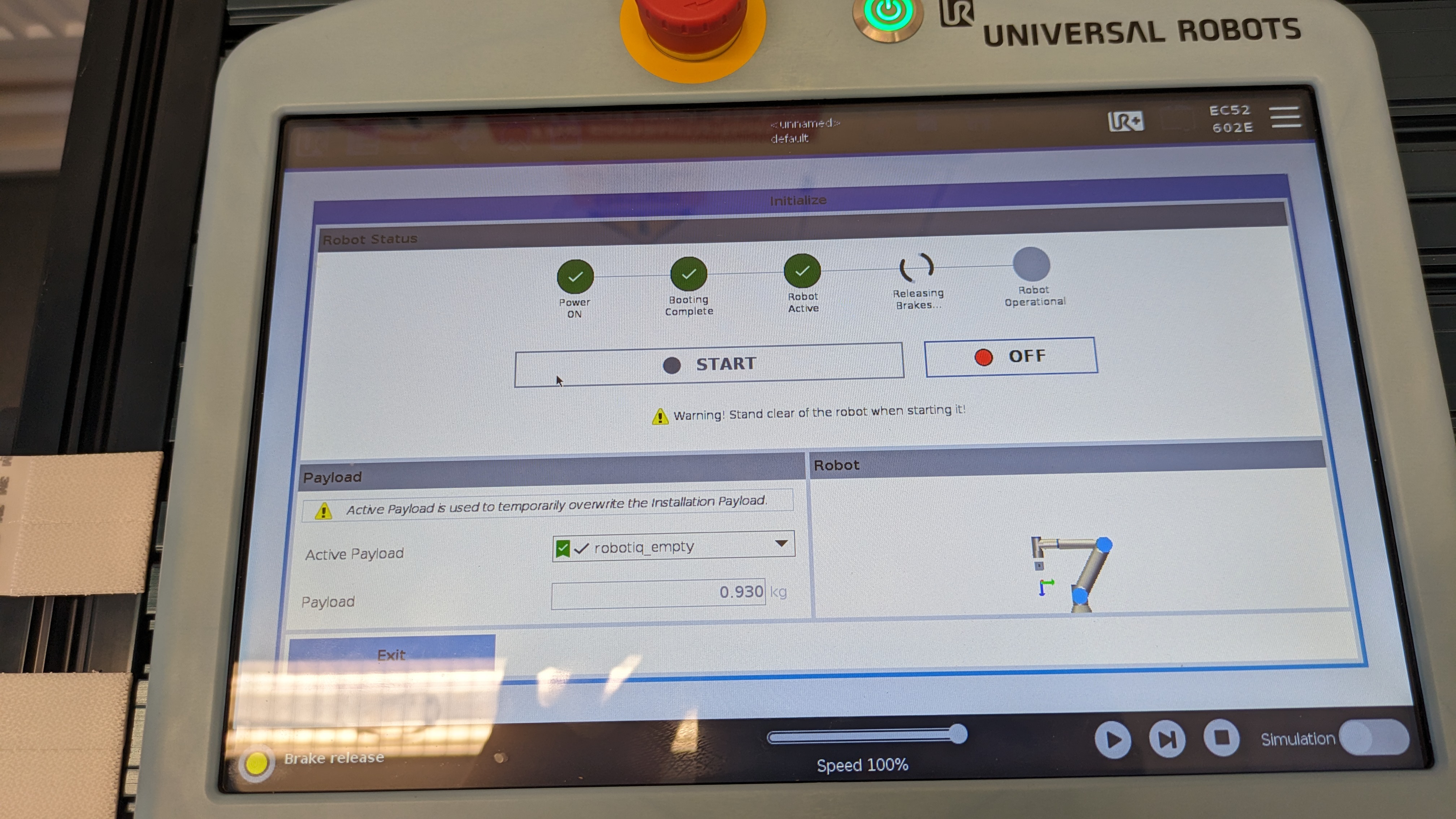
- You will get a pop up screen as shown below and within the pop up screen, click on the "ON" button. You will notice that the circles with the status will change to green and the status will change as well.
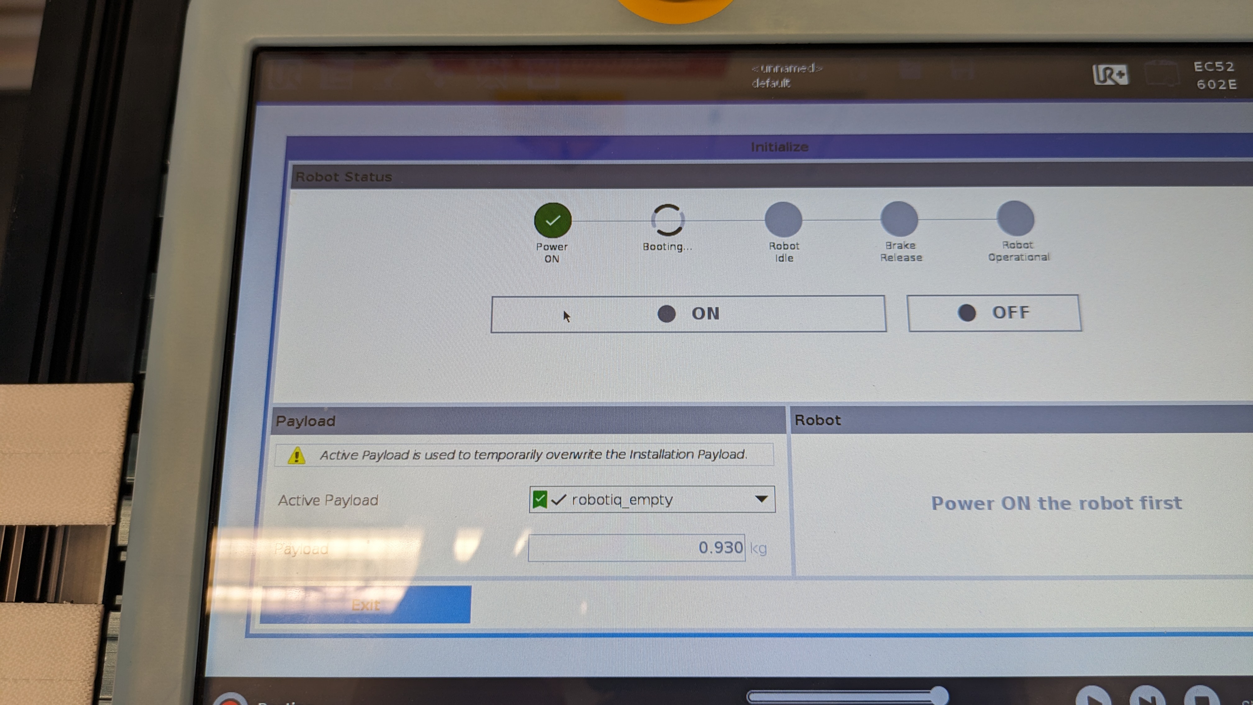
- After a couple of seconds, you should see that the "ON" button would have been replaced with the "START" button. Now, click on the "START" button, you will hear some clicking noises coming from the robot arm, which indicates the breaks of the robot arm are being released.
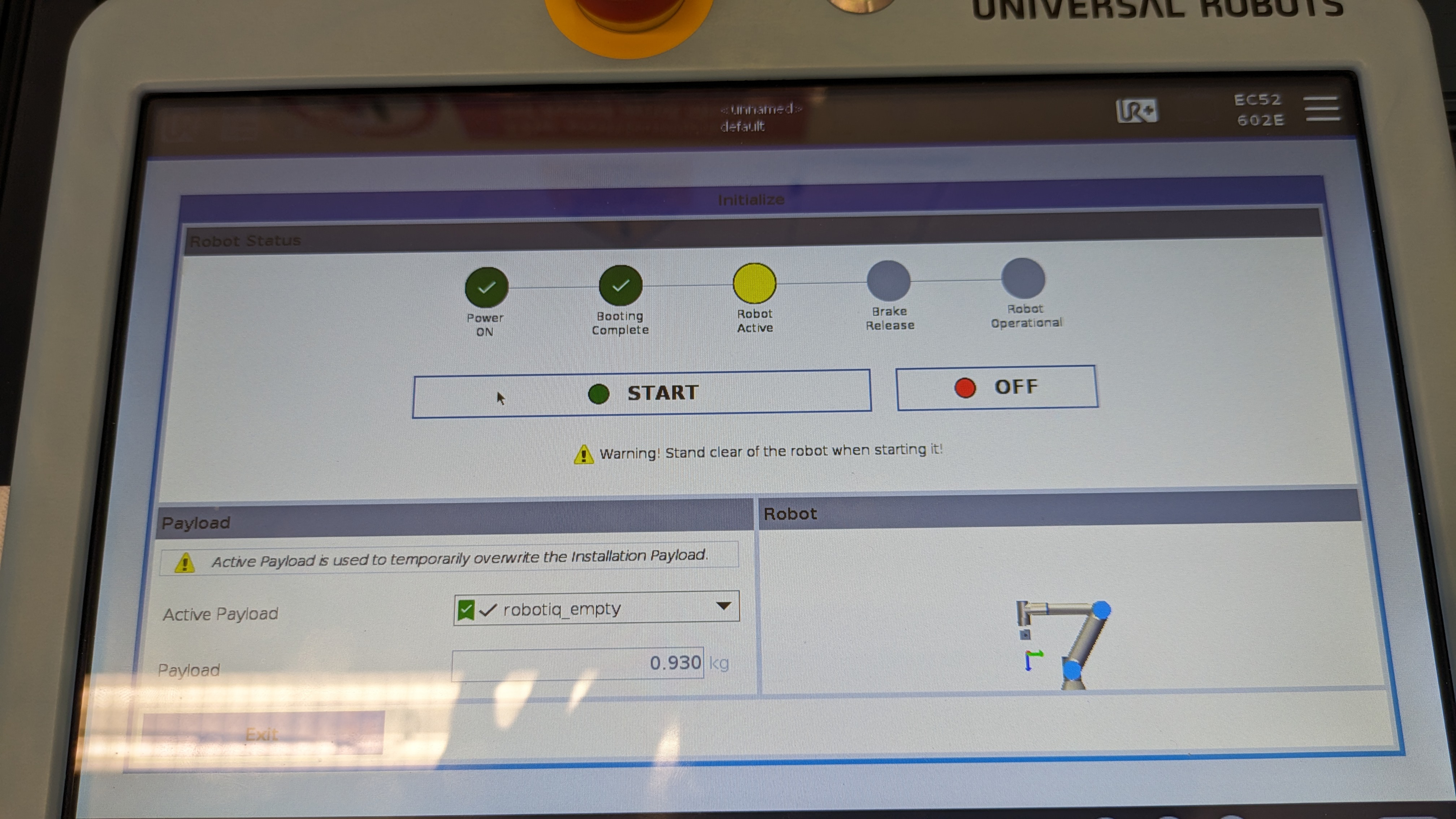
- If everything goes well, you will see that all the circles will be green and if you look over to the bottom left corner of the teach pendant, the red button we initially clicked is now green and it will also say "Normal" next to it.
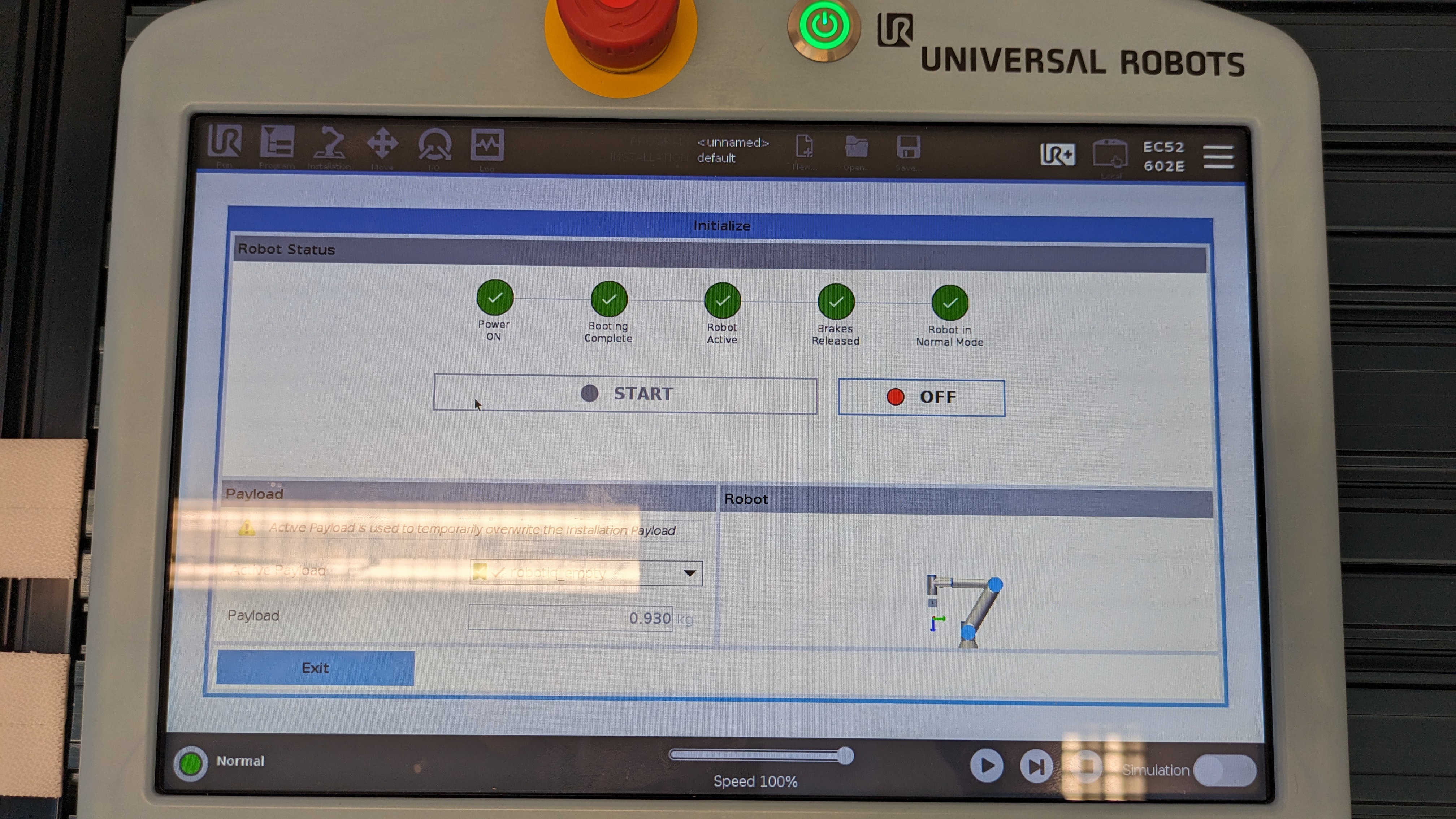
- Now you can exit this screen by clicking on the "EXIT" button located at the bottom left of the screen.

Power off
To power off the robot, press down on the power button that is located at the top of the teach pendant and then select "Power off" on the pop up. If you were working on a program and want to save it click on "save program" otherwise click "Discard".
Controlling the UR5e using the teach pendant
There are 2 ways to control the UR5e robotic arm.
- Using the teach pendant.
- External control using RTDE, URscript or ROS2.
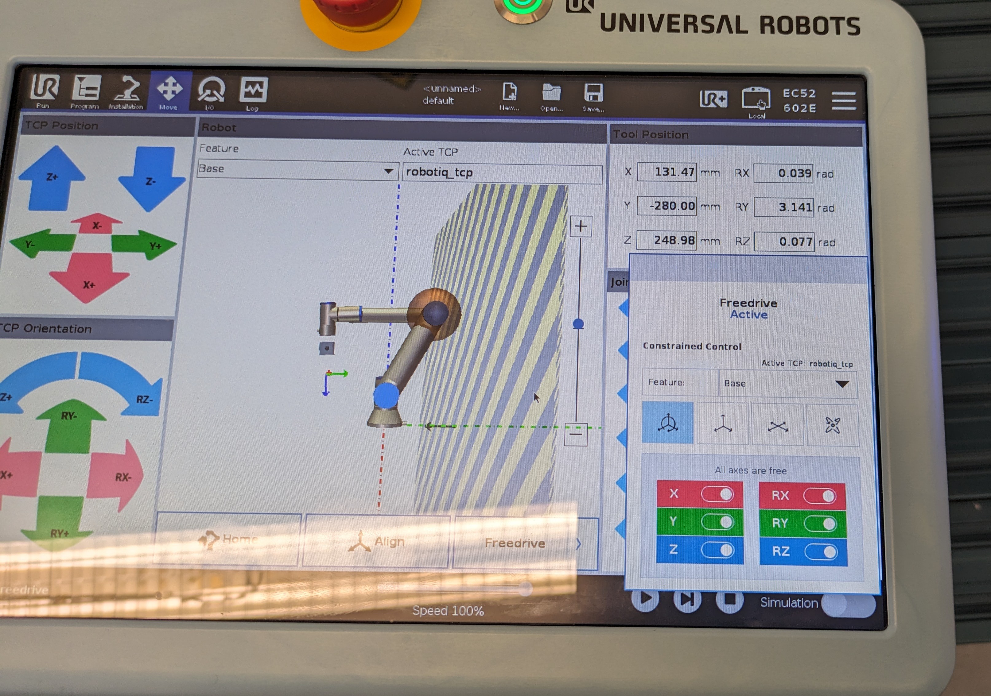
Moving the UR5e
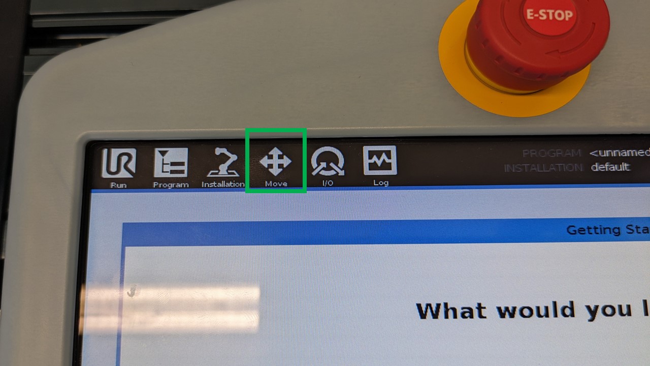
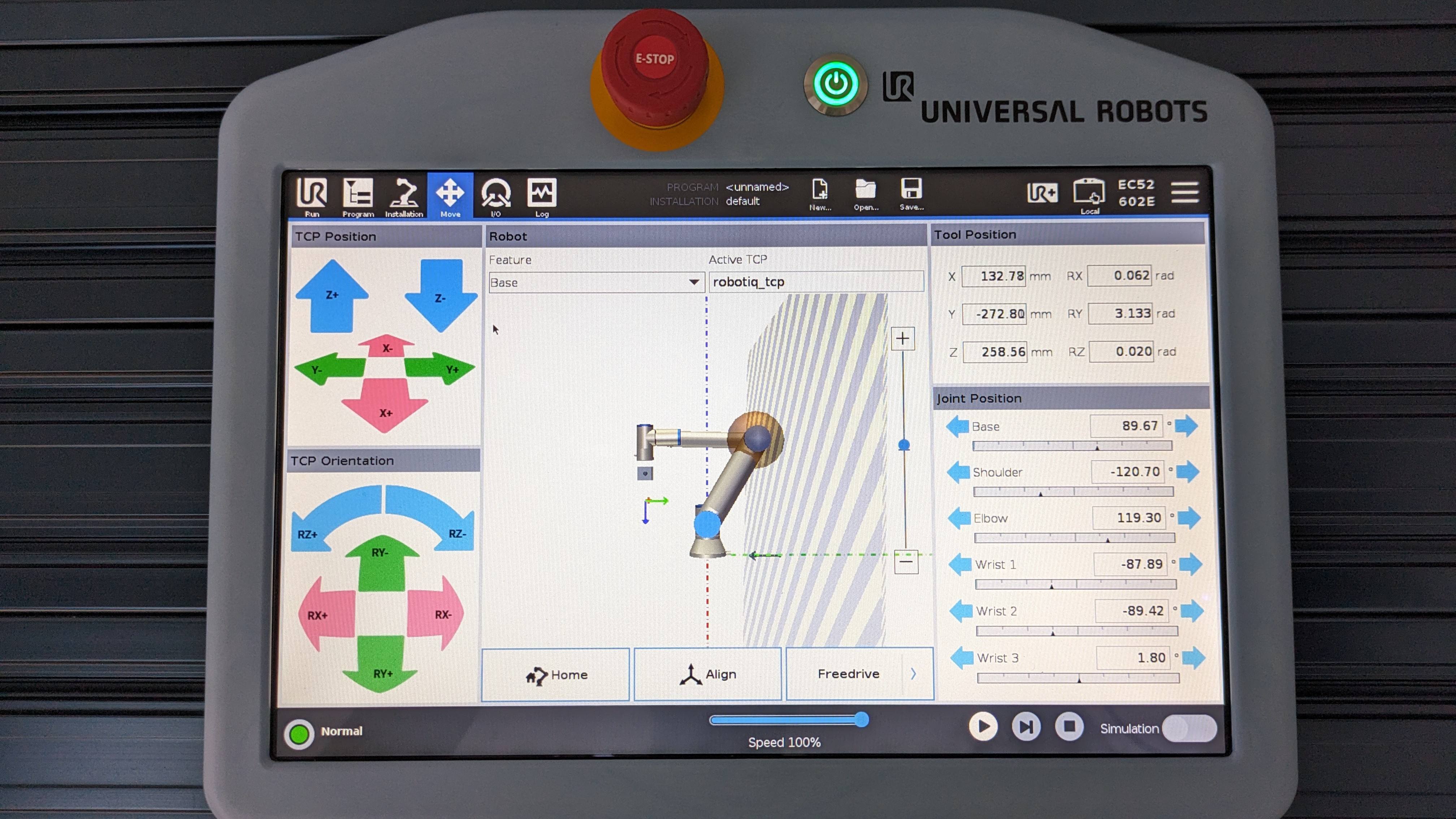
You can move the robot using different methods but to do that, you must first be in the move menu or setting a way point in a program. To navigate to the move button, click on the button that says "Move" which is located at the top left of the screen. It looks like the image below.
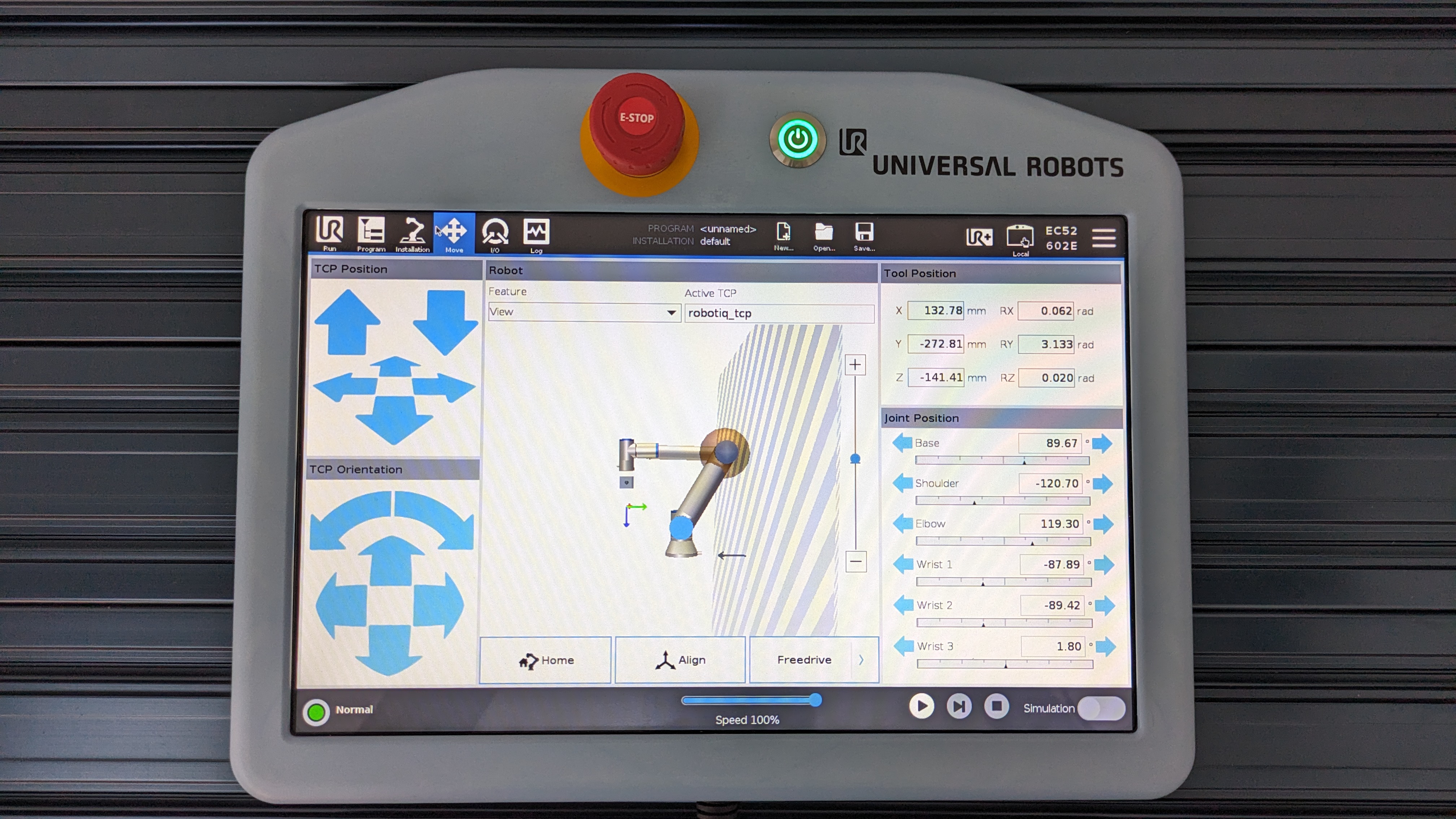
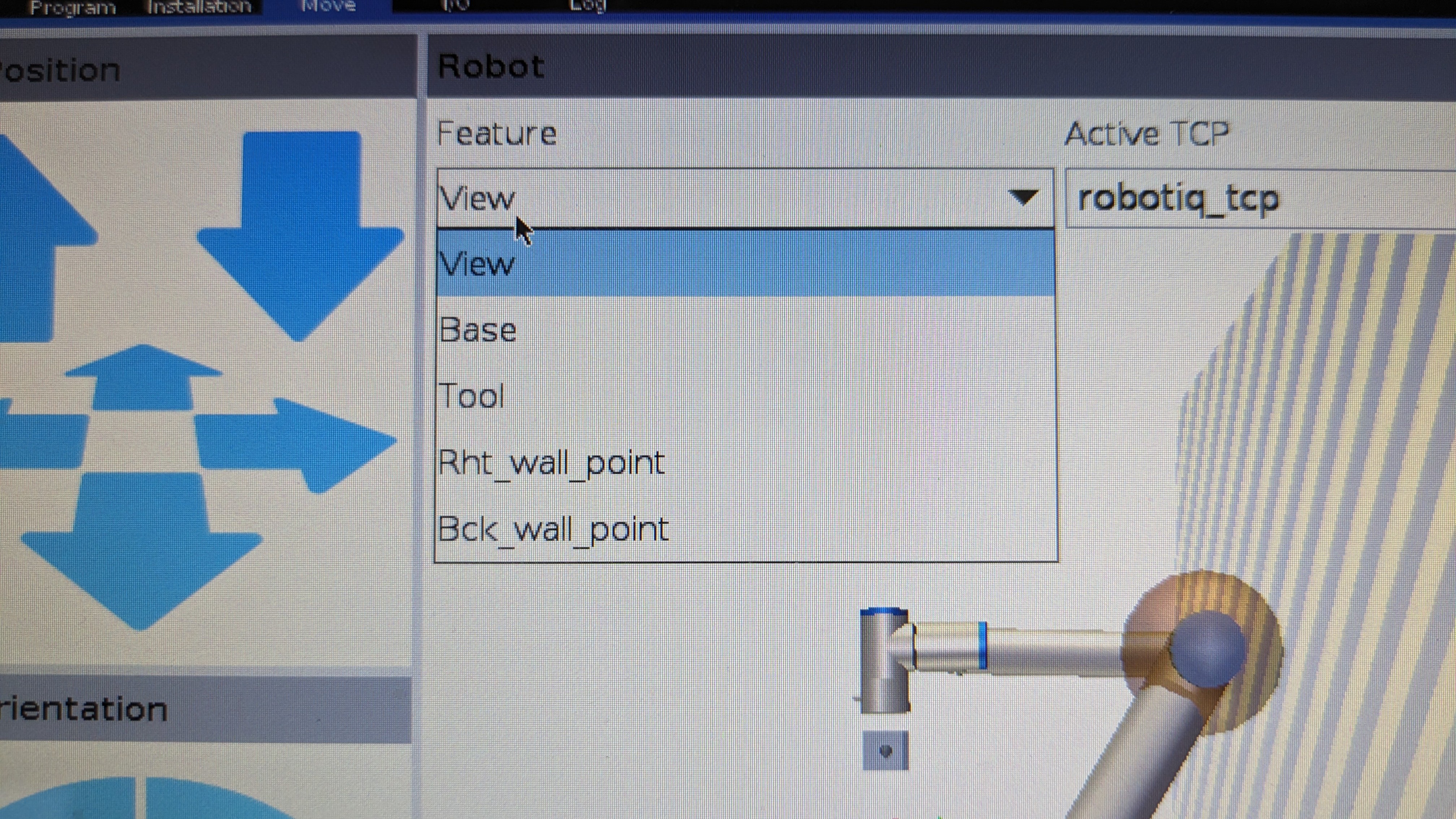
Once you are in the move menu, make sure to change the option in Feature to "Base" instead of "View", so that your reference point is from the base of the robot arm instead of the virtual camera. To do that click on the drop down that is below feature and select "Base". You should see that the arrow keys on the left have changed in colour.
- Jogging the robot - To jog the robot, press and hold one of the arrow keys on the left hand side of the screen as shown below.
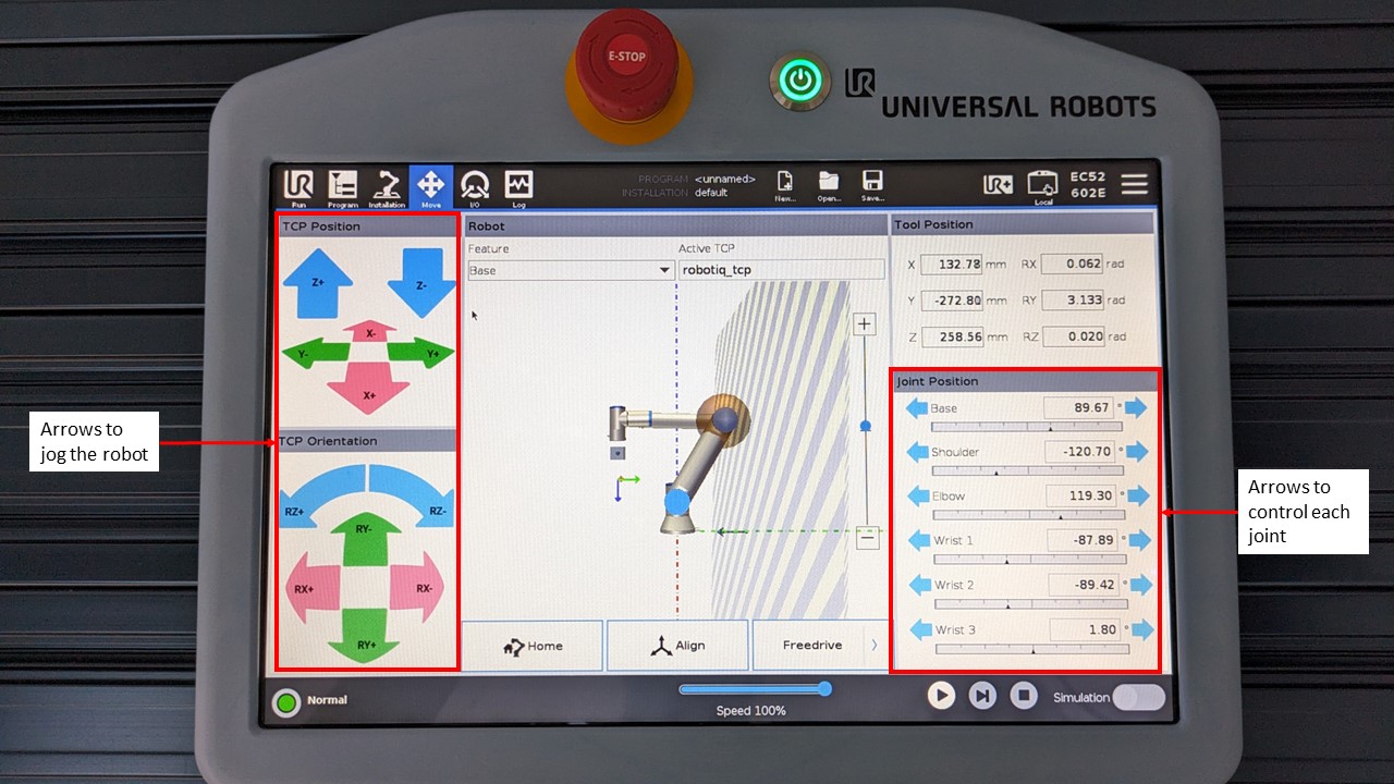
-
Move each joint - To move each joint of the robot individually press and hold the arrows on the right hand side of the screen as shown above.
-
Freedrive mode
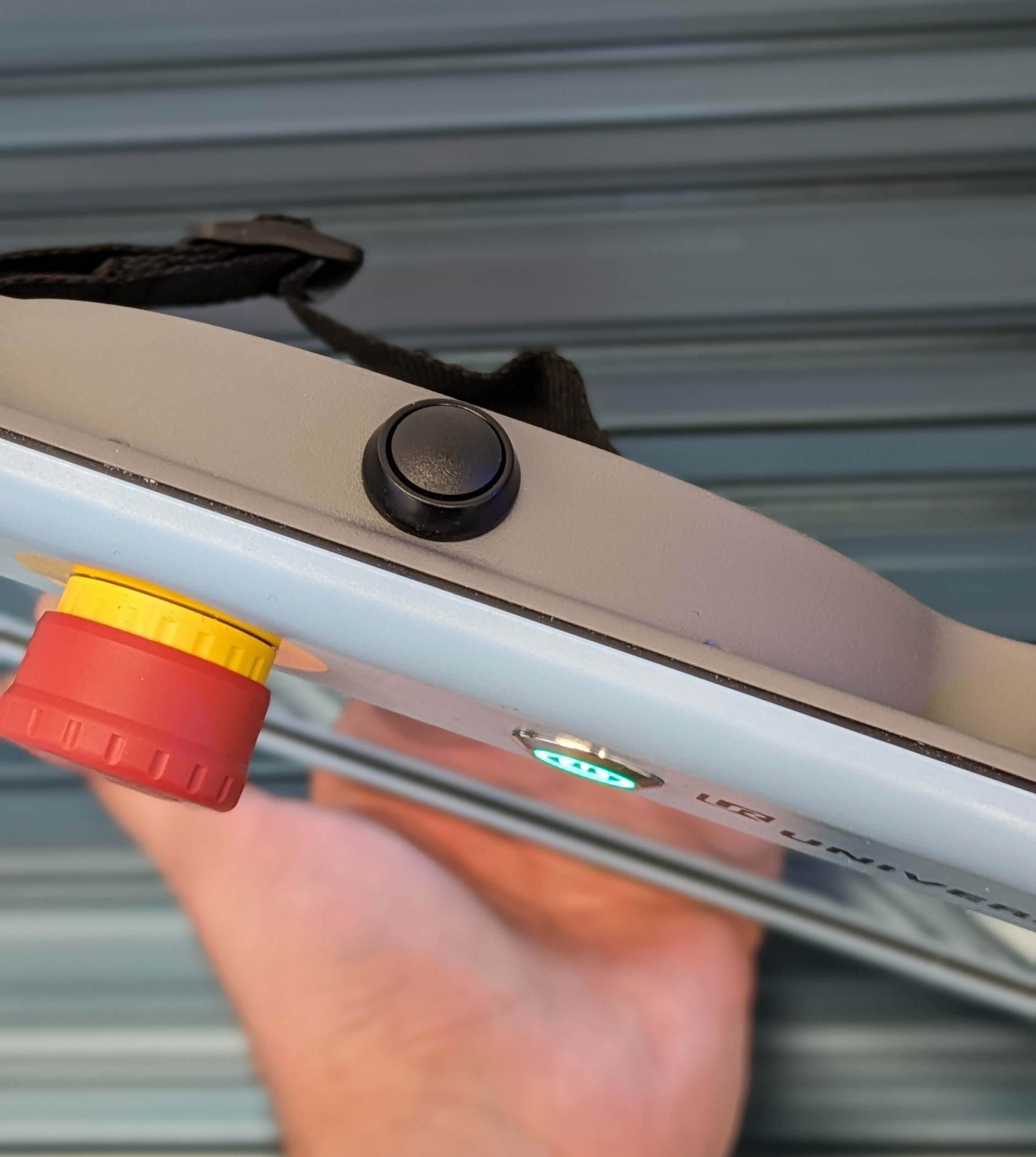
- To move the robot using Freedrive, with one hand press and hold the black button that is on top of the teach pendant. You will see a pop on the teach pendant that says "Freedrive Active".
- Place your other hand on the flange of the robot. Now drag the robot with your arm to a desired position.
Basic motion programming for UR5e with 2F-85 gripper
The main concepts behind programming the UR5e are move commands and waypoints.
Move command
Move commands define how you would like the robot to move in order to reach a certain waypoint.
There are 3 move commands you can choose from:
- MoveJ - Stands for Move Joint. This means, given two distant waypoints A & B, the robot will take the fastest and easiest route from A to B and vice versa.
- MoveL - Stand for Move Linear. This means, given two distant waypoints A & B, the robot will move in a straight line from A to B or vice versa.
- MoveP - Stands for Move Process. With this move command, the robot will move through multiple waypoints with a constant speed. You can also make circles using this move command.
Waypoints
Waypoints are 3D coordinates within the robot's workspace set by the user.
Creating a simple program
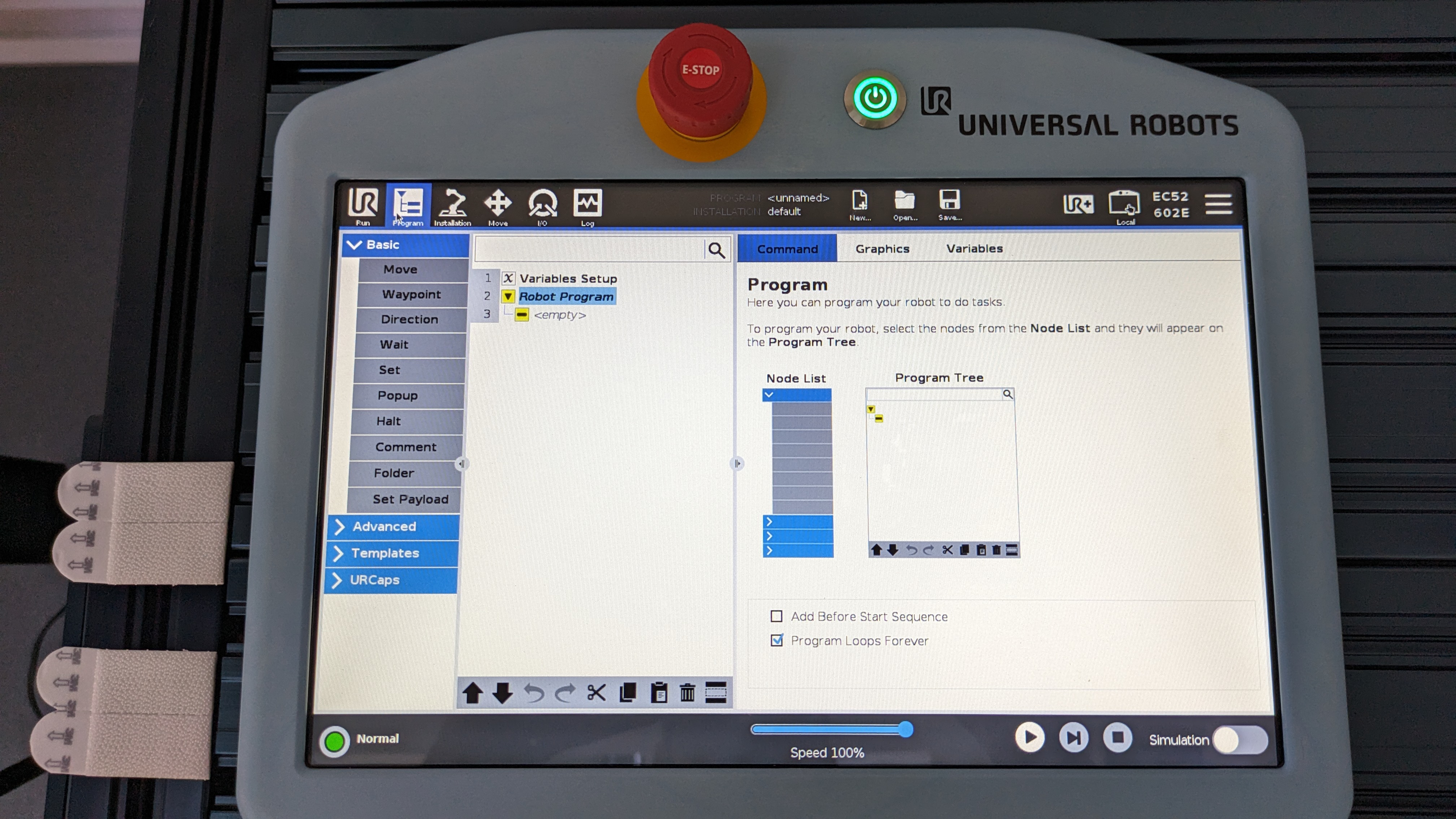
In order to create a program, ensure that you are in the programming menu.
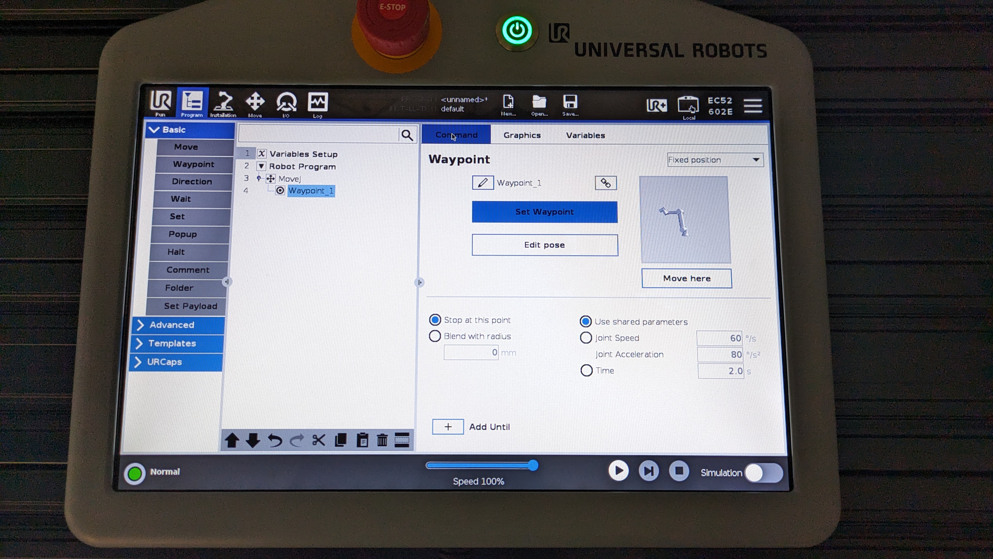
Now, your screen should look something like the one below.
- To add a move command, select "move" which is within the "Basic" dropdown list. You should see that a move command with
Waypoint_1has been inserted beneath Robot Program as shown below.
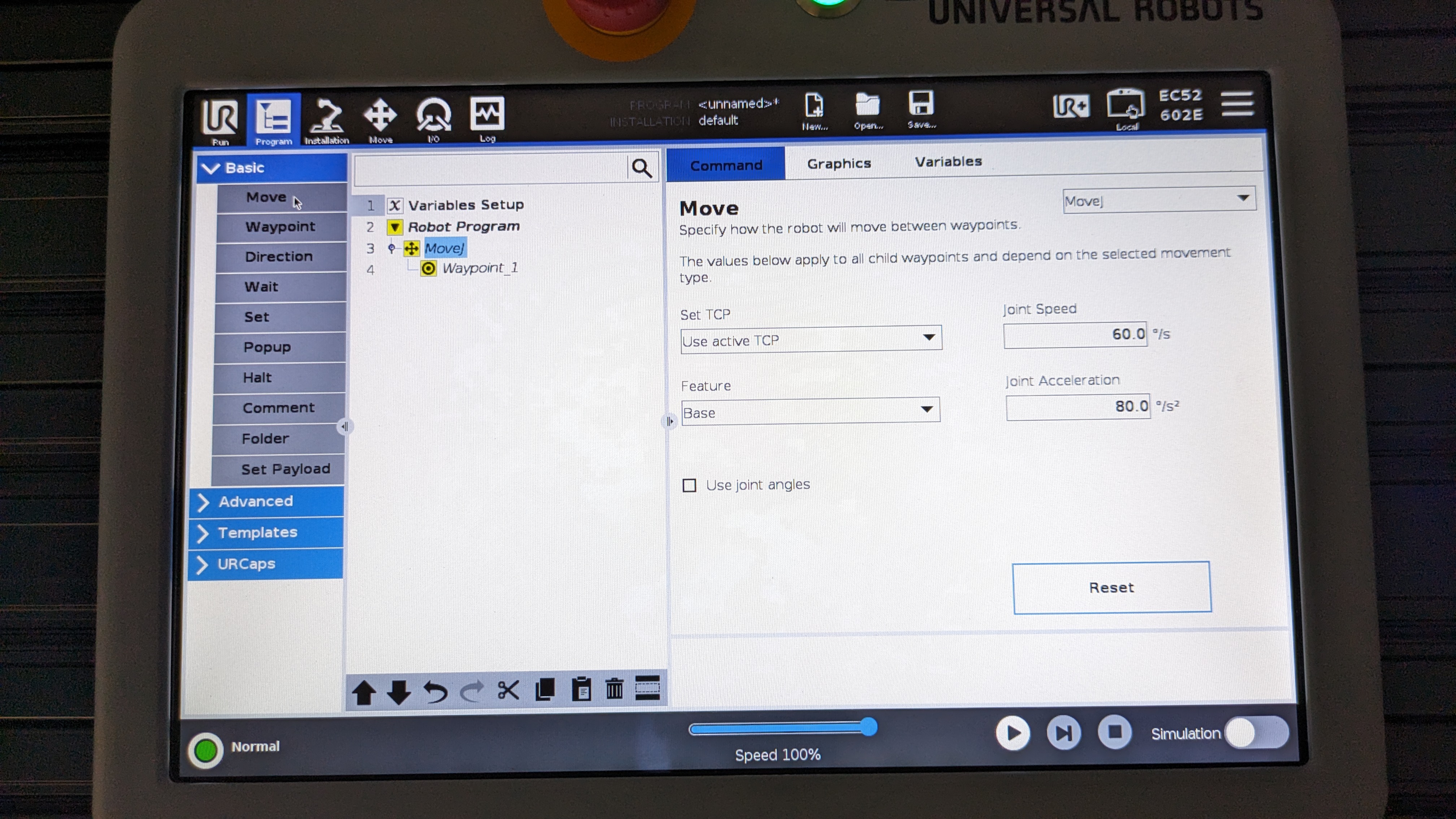
The default move command is MoveJ but if you want to change it, click on the drop down to the left for the screen which says MoveJ and select another move command from the dropdown list.
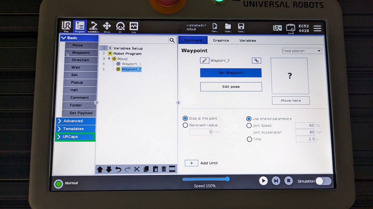
- Click on
Waypoint_1and you should see the right side of the screen change to the image below.
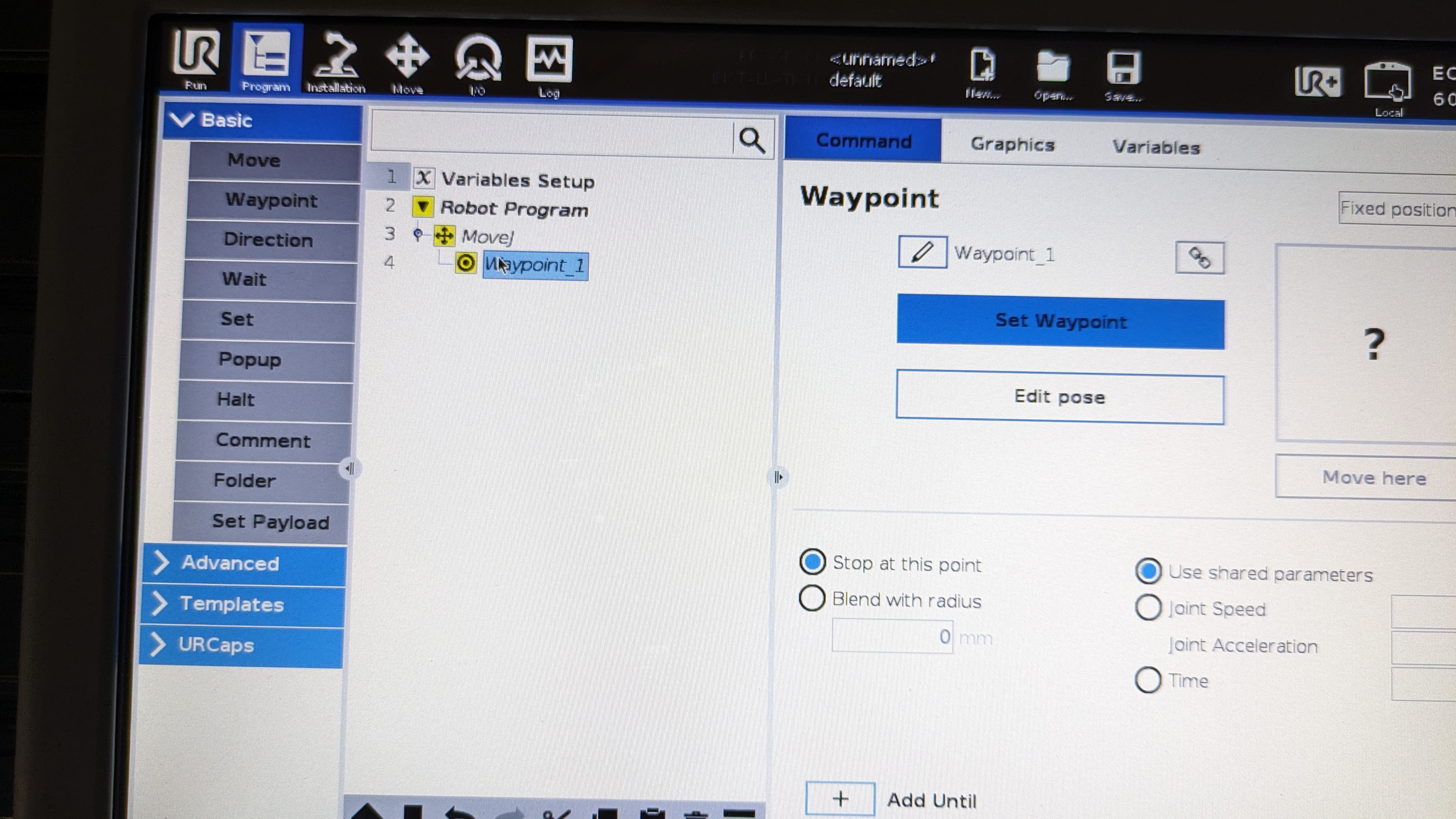
- Click on the "Set Waypoint" button. This will change the screen to a similar screen from the move menu as shown below. But the main difference is that you now have an "OK" and "Cancel" button to set or cancel a waypoint.
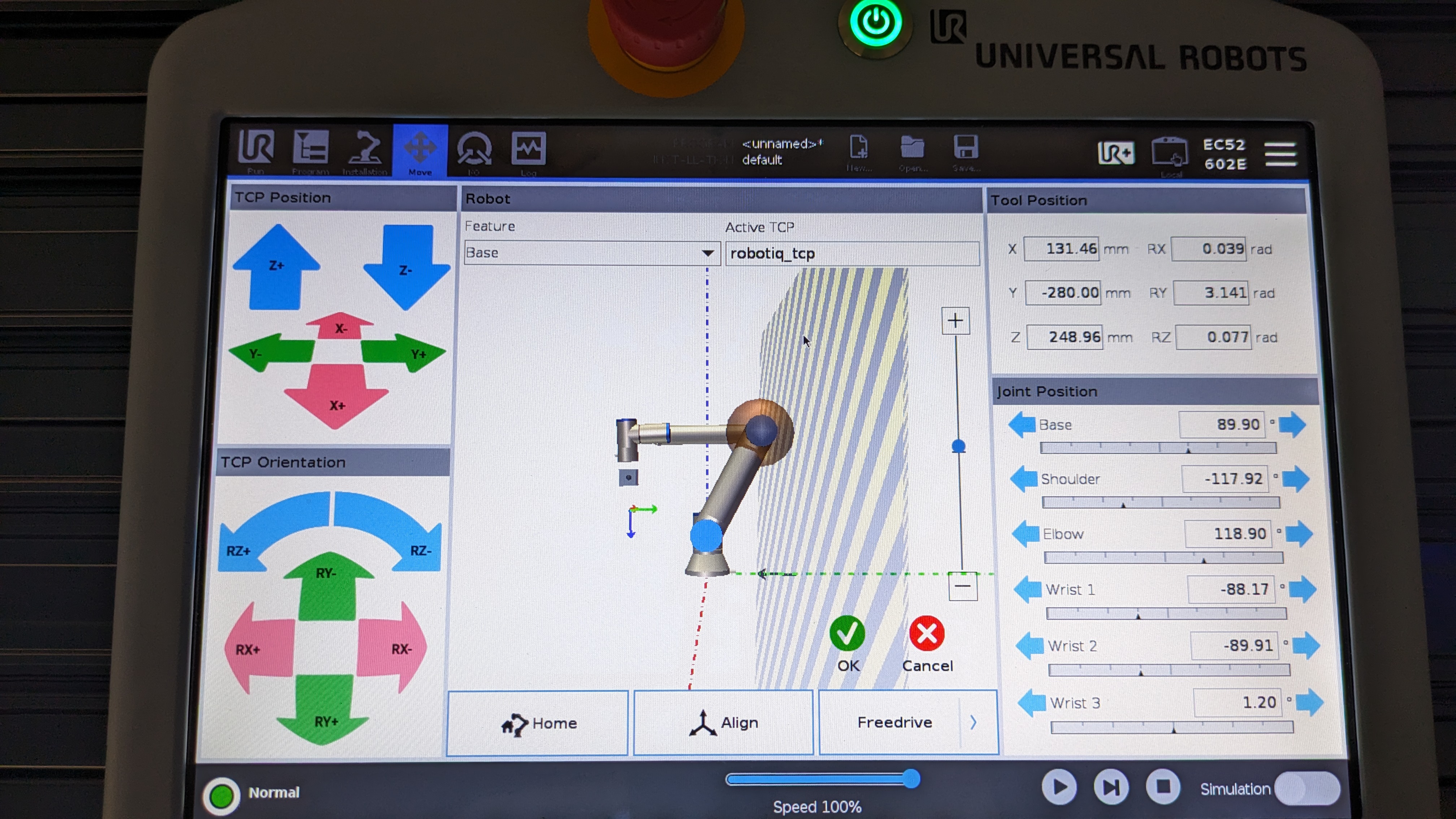
- If you want to set the current location of the robot as a waypoint then click on "OK". If you want to set a new location as a waypoint, then jog, drive or Freedrive the robot to a desired location within the workspace and click "OK". You will see that
Waypoint_1is no longer highlighted in yellow, meaning the waypoint has been set successfully.
- If you would like to add another waypoint, click on "Waypoint" which is within Basic drop down list. Another waypoint called
Waypoint_2will be added into your move command.

- To set your newly added waypoint, repeat steps 4 and 5.
Good practices
- Do not nest move commands, i.e. do not create a move command within a move command.
- Name your move commands and waypoints so that you know what is happening when the robot is about to execute it.
Controlling the Robotiq 2F-85 adaptive gripper
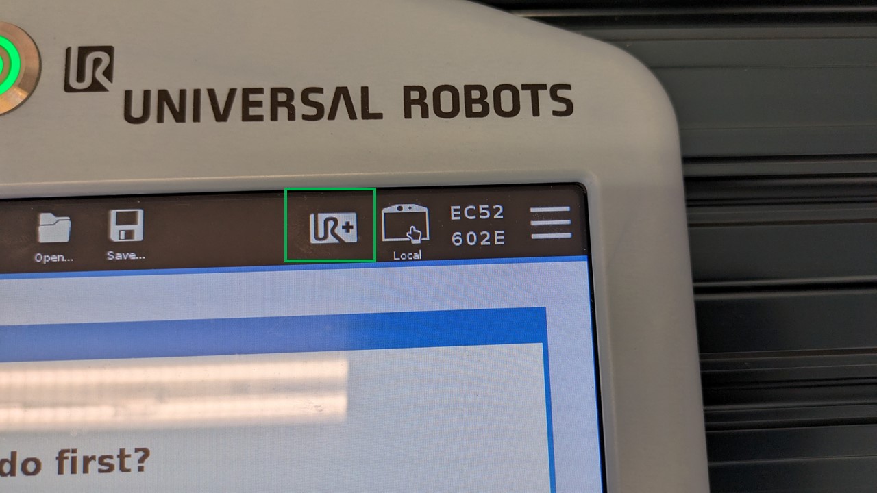
To control the robotiq gripper using the teach pendant, click on the "UR+" button located on the top right of the screen as shown below.
This will show a pop up screen as shown below.
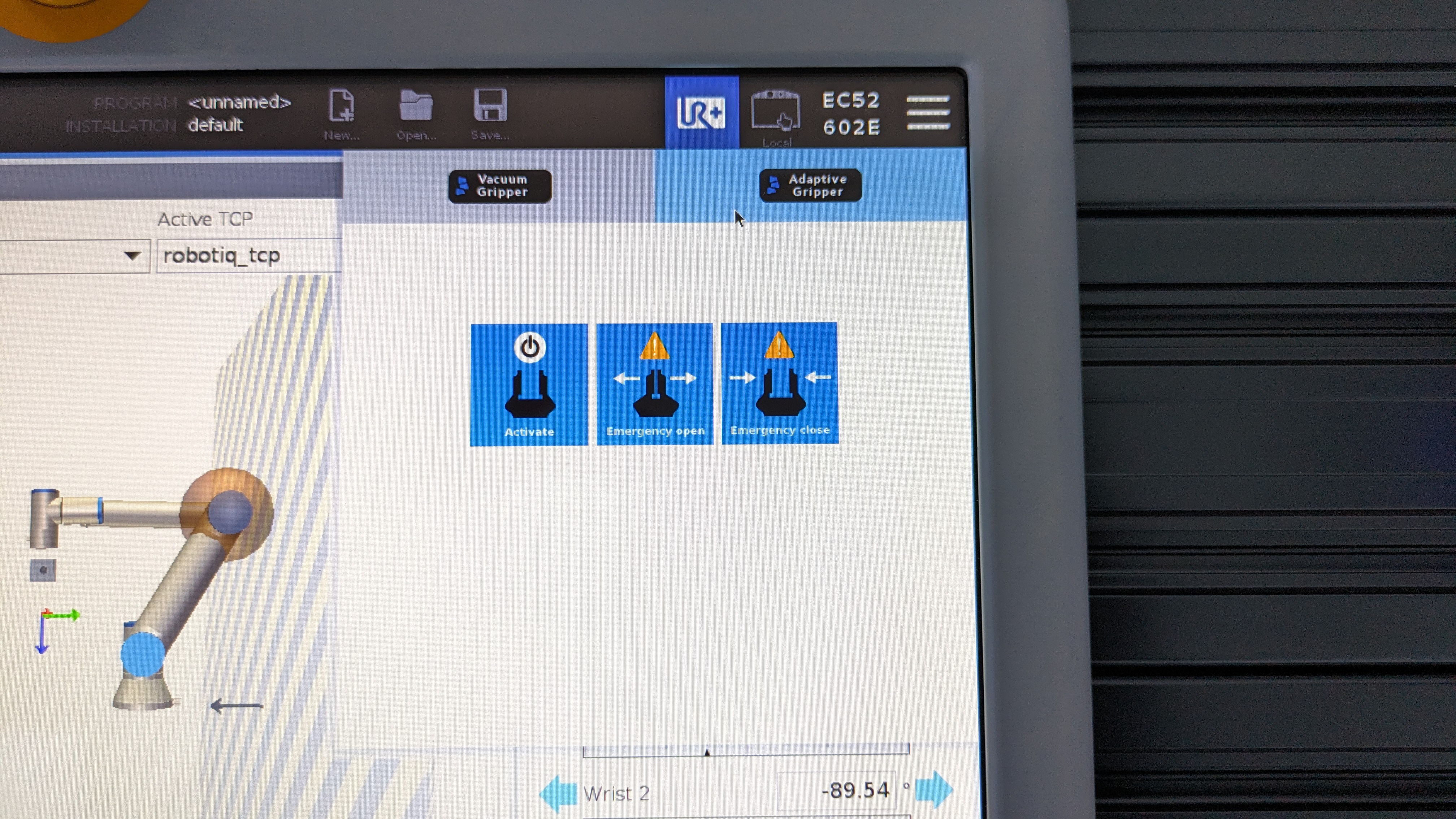
Select "Adaptive Gripper" as that is the gripper we have and then click on "Activate". You will see the robotiq gripper will close and open.
Once the gripper is active you will see that the pop up will change and give you some options to control the gripper as shown below.
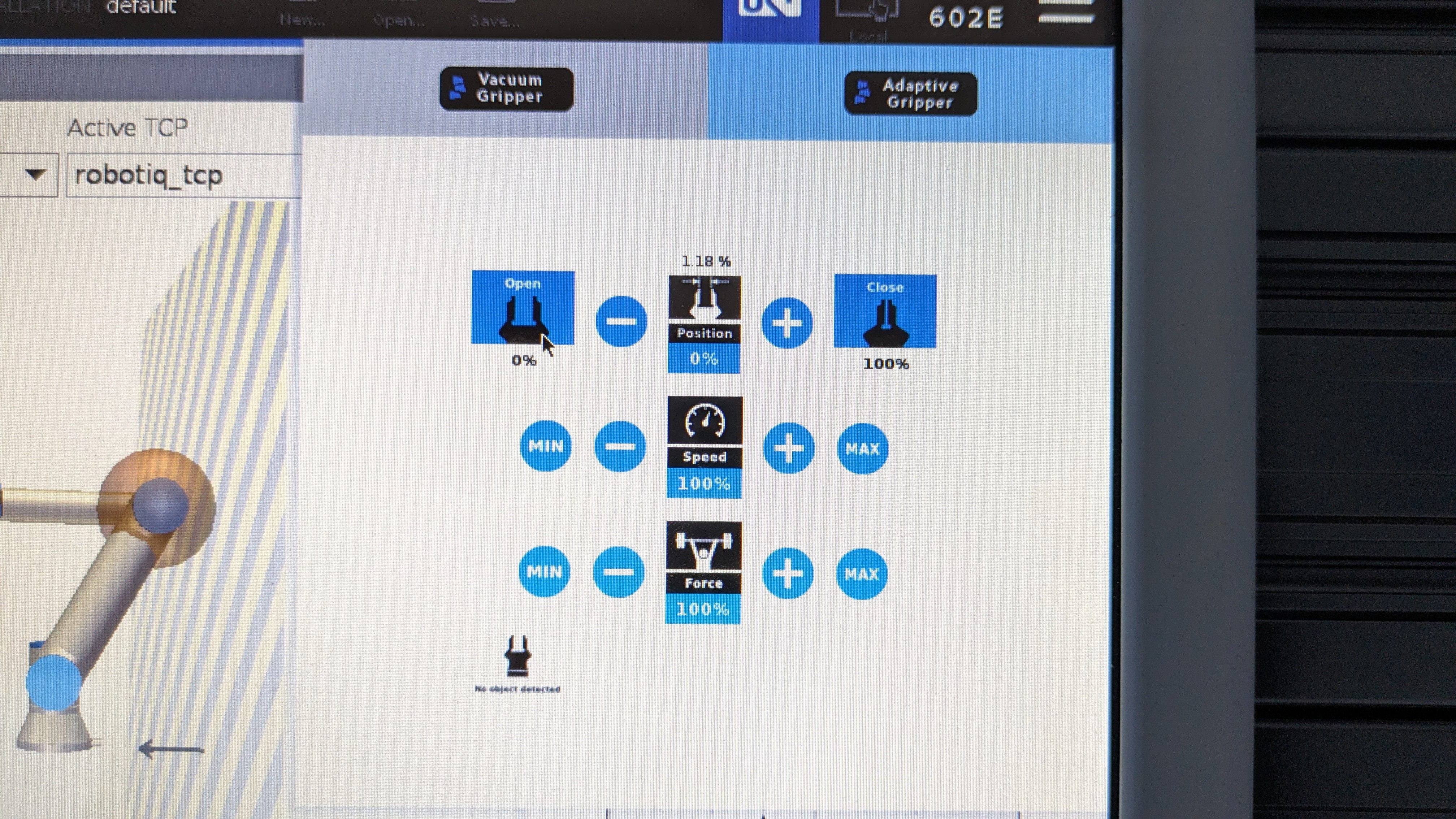
Now, you can open or close the gripper, control the speed at which it opens or closes and the force / grip strength of the gripper.
Adding gripper command to your program
To program the gripper so that it opens or closes when the robot has reached a point, navigate to the program menu and ensure you have set your waypoints by following the instructions in the previous section.
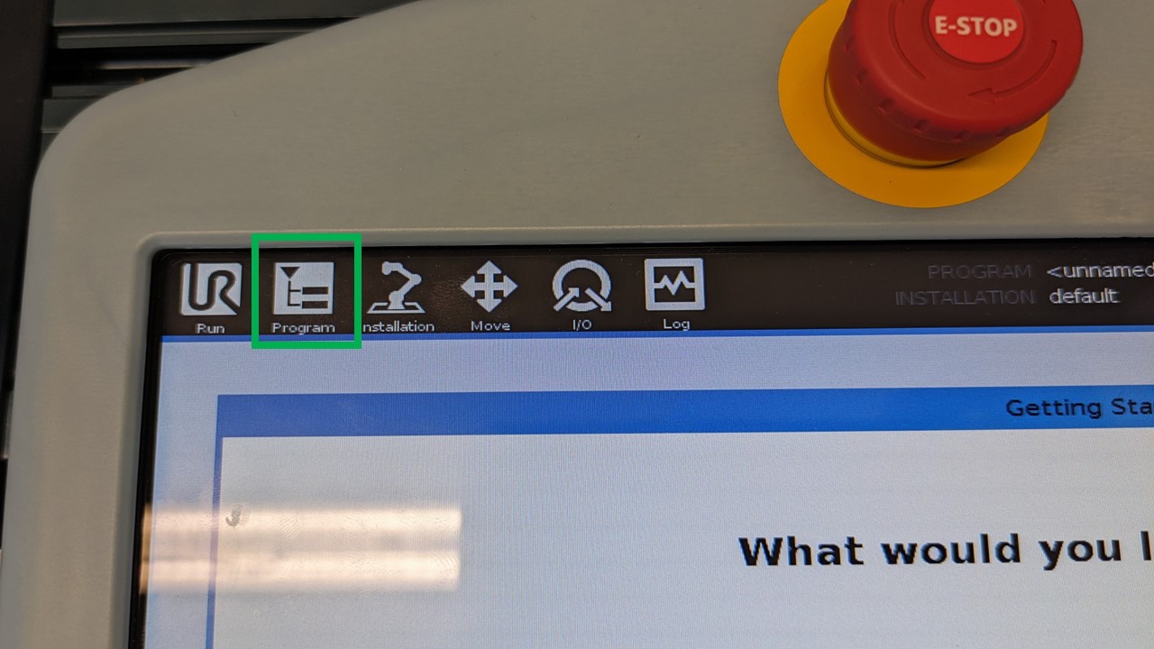
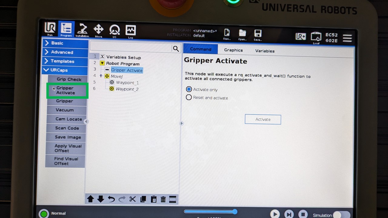
- Select "URCaps" drop down which is on the left side of the screen within the program menu. It is also shown in the image below with a green box.
- Select "Gripper Activate" and make sure this is placed at the beginning of your program.
- Select the waypoint where you want to add the gripper command.
If you place a gripper command after a waypoint, then it will be executed once the waypoint is reached, if the gripper command is placed before a waypoint, it will be executed before the robot starts moving to the waypoint.
- To add a gripper command, select "Gripper" from the URCaps dropdown.
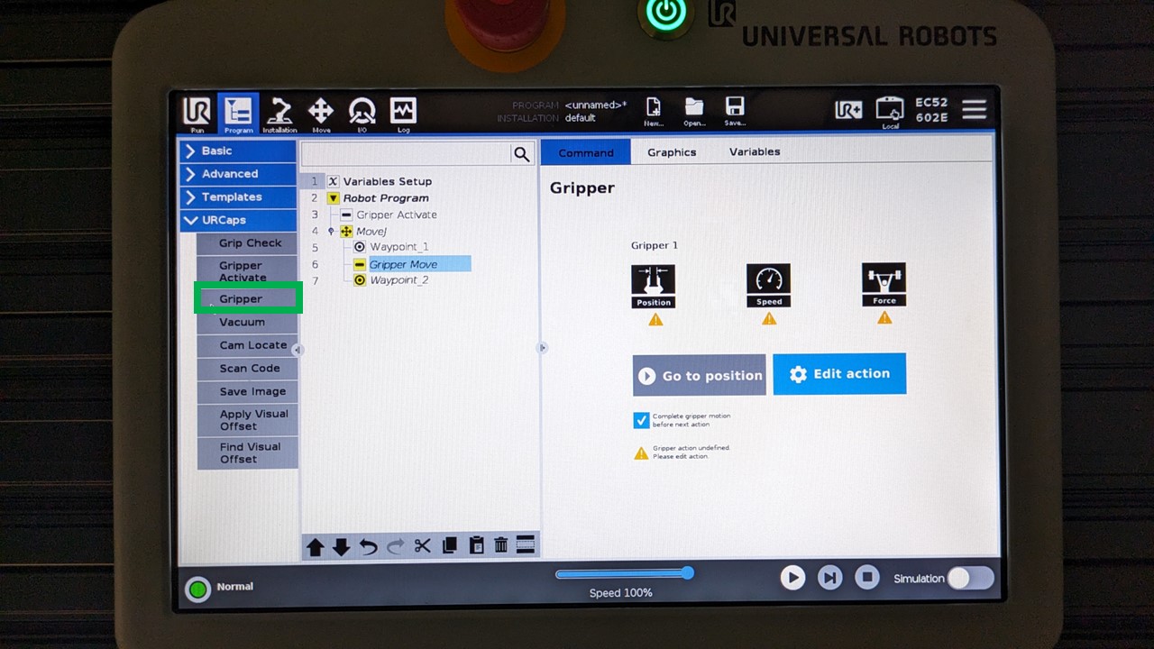
-
One the right side of the screen, you should now see some options related to the gripper.
-
Click on "Edit action" and then choose whether you would like to open or close the gripper.
Do not choose a percentage for opening or closing the gripper as this could cause issues. The gripper should either be open (0%) or close (100%).
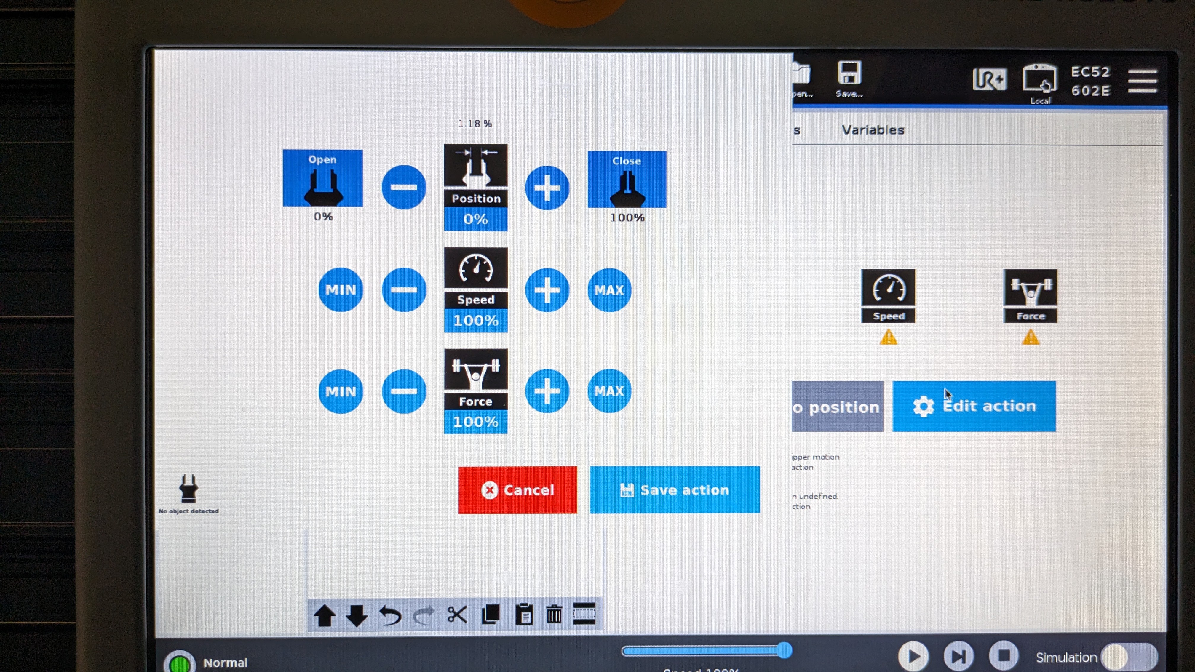
-
Adjust the speed and force of the gripper according to your need. Click on "Save action" when you are happy with your settings.
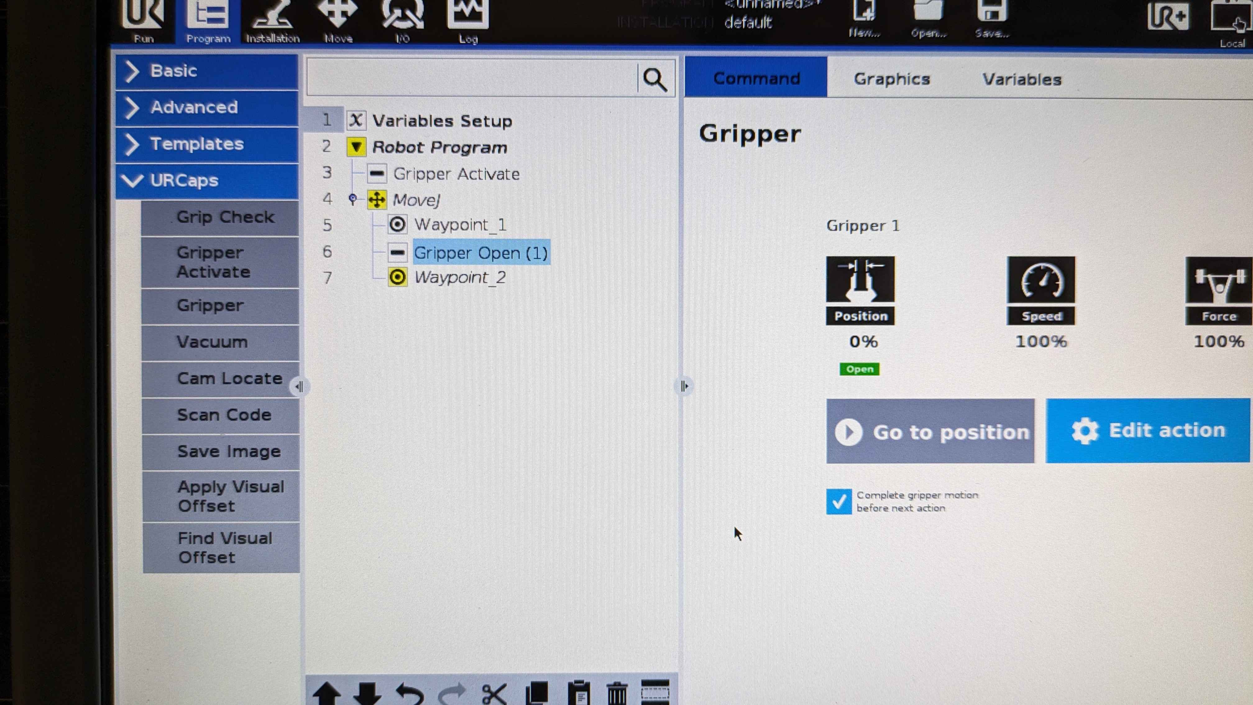
-
If all goes well, you should see the gripper command "Gripper Open" or "Gripper Close" based on which action you have chosen.
Controllling the UR5e through software
There are many ways of controlling the UR5e through your own software or code but the easiest and most straight forward way is through the ur_rtde library.
Detailed documentation about the library is given here.
Establishing connection between your machine and the robot
Before we get started with the library, we must first establish a connection between our machine and the robot. Since the robot has no wireless interface, this will be done through a wired connection via an ethernet cable. Please follow the steps below to connect your machine to the robot.
Locate the ethernet cable attached to the robot and connect it to your machine's ethernet port (mac users will need an adapeter such as a usb to ethernet port adapter).
The next step is a bit different based on the operating system you are using therefore I have broken them to subsections that are give below. We are updating our IPv4 settings to point to the robot's IP. When changing the settings, please use the parameters given below.
| Address | Netmask | Gateway |
|---|---|---|
| 192.168.56.4 | 255.255.255.0 | 192.168.56.5 |
-
For Linux (ubuntu): Open
Settings>Network> in the wired section click on the settings button > selectIPv4on the pop-up and select manual. In the addresses section enter the parameters given above. -
For Windows: Please have a look this video and when you are in the IPv4 settings, enter the parameters given above.
-
For Mac: (instrructions coming soon..)
Once you have entered these parameters, please check if you can communicate with the robot. This is done using the ping command. Open up your terminal or command prompt and run the command ping 192.168.56.5.
If successful you should get something like this as your output:
Reply from 192.168.56.5 bytes=32 time=378ms TTL=64
if not, please double check if you have entered the parameters correctly in their respective sections.
If that doesn't work, please consult with a technician.
Installing ur_rtde
Quick Install
For python usage: python -m pip install ur-rtde or python3 -m pip install r-rtde
Note for mac users, the pip instal might not work in some cases and if that happens please follows the instructions for source install given below.
For cpp usage:
sudo add-apt-repository ppa:sdurobotics/ur-rtdesudo apt-get updatesudo apt install librtde librtde-dev
Source Install
git clone https://gitlab.com/sdurobotics/ur_rtde.git
cd ur_rtde
git submodule update --init --recursive
mkdir build
cd build
cmake ..
make
sudo make install
Run Example Scripts
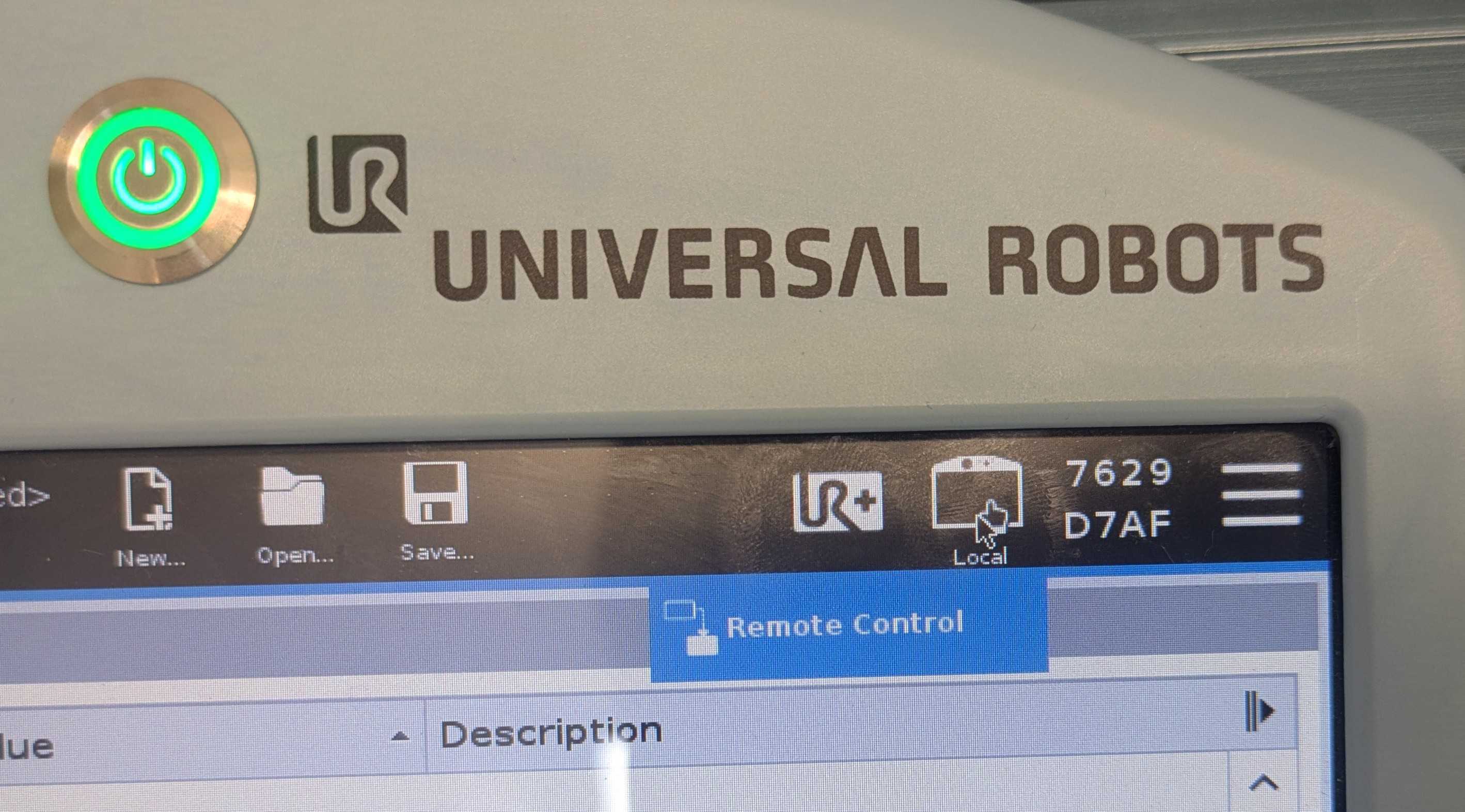
Before running the example scripts, please make sure to change from local to remote control mode in the teach pendant.
Once you have successfuly installed ur_rtde and have switched to remote control mode on the teach pendant, please try out some these example scips given here
Specification
Additional resources
- UR5e website
- UR5e user manual
- Robotiq 2F-85 user manual
- Universal Robots e-learning
- Universal Robots academy
- UR5e general risk assessment
- ur_rtde docs
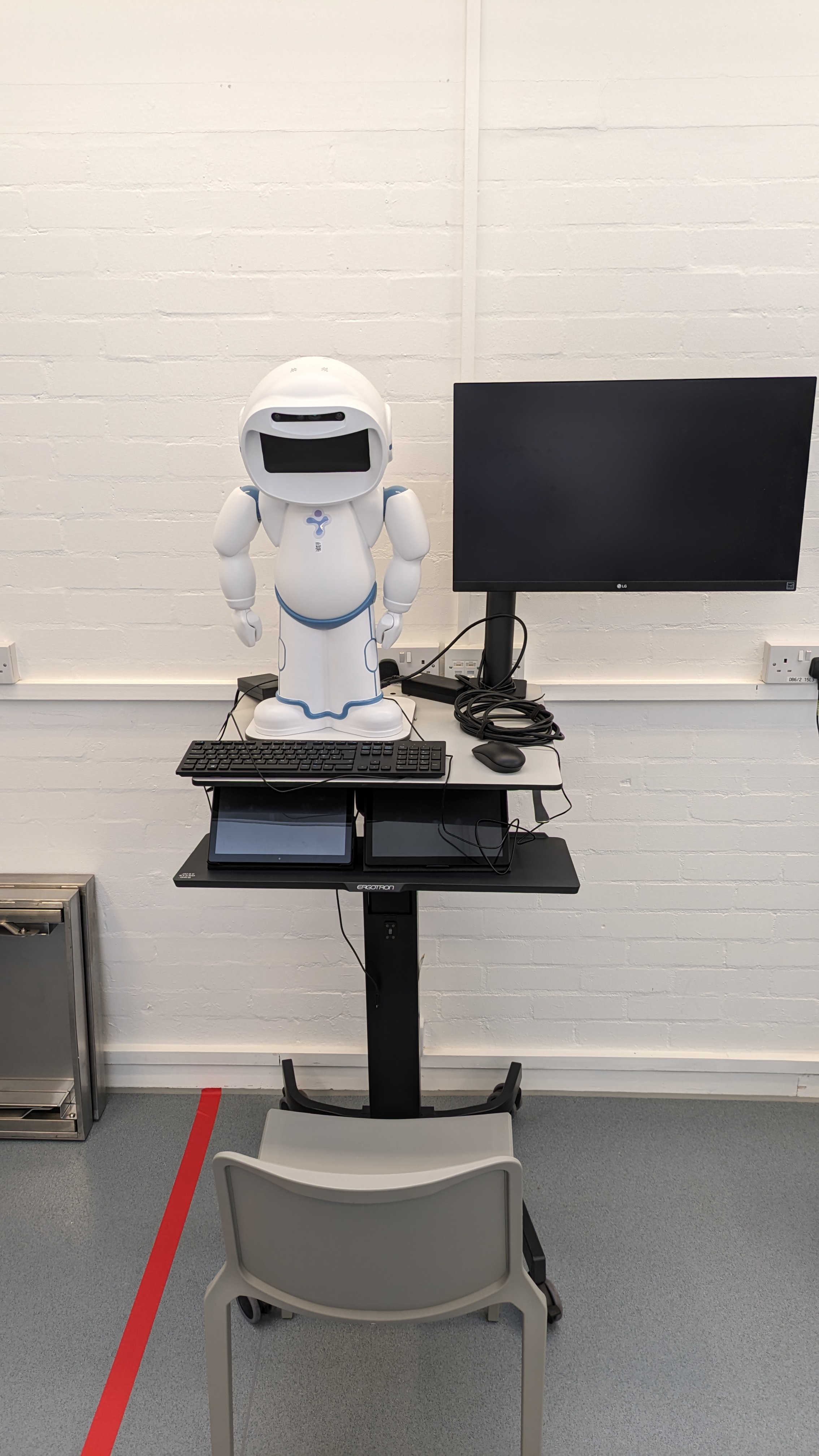
Using QTrobot
What is it?
QTrobot is described an expressive humanoid social robot.
What can it do?
Using its inbuilt functions and APIs you can get it do some interesting things. Have a look at its competences page to get a full understanding of its capabalities.
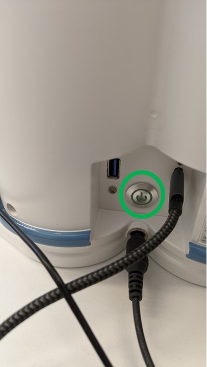
Powering on/off
Power on
To power on QTrobot, press down on the power button that is located behind the robot. You will see QT's head raise up and a face will be displayed on the screen that's on its head.
Power off
To power off QTrobot, simply press down on the power button. You should see the motors of the robot disengage and after a couple of minutes, the screeen on QT's face will flash blue. After this, switch off the powersupply to the robot. This concludes the power off procedure.
How can I program it?
There are two ways of programming QTRobot.
Everything you need to get started with programming the QTrobot can be found here
Additional Resources
- LuxAI S.A. githubpage - click here
- QTrobot questions and answers - click here
Using Turtlebot4
What is it?
The Turtlebot 4 is the latest addition to the Turtlebot series, which is a popular robotics research and education platform. The Turtlebot 4 shares the same base as the iRobot Create 3 and it is powered by ROS2 (Robot Operating System 2). For reference, iRobot are the creators of the famous Roomba Robot Vaccums.
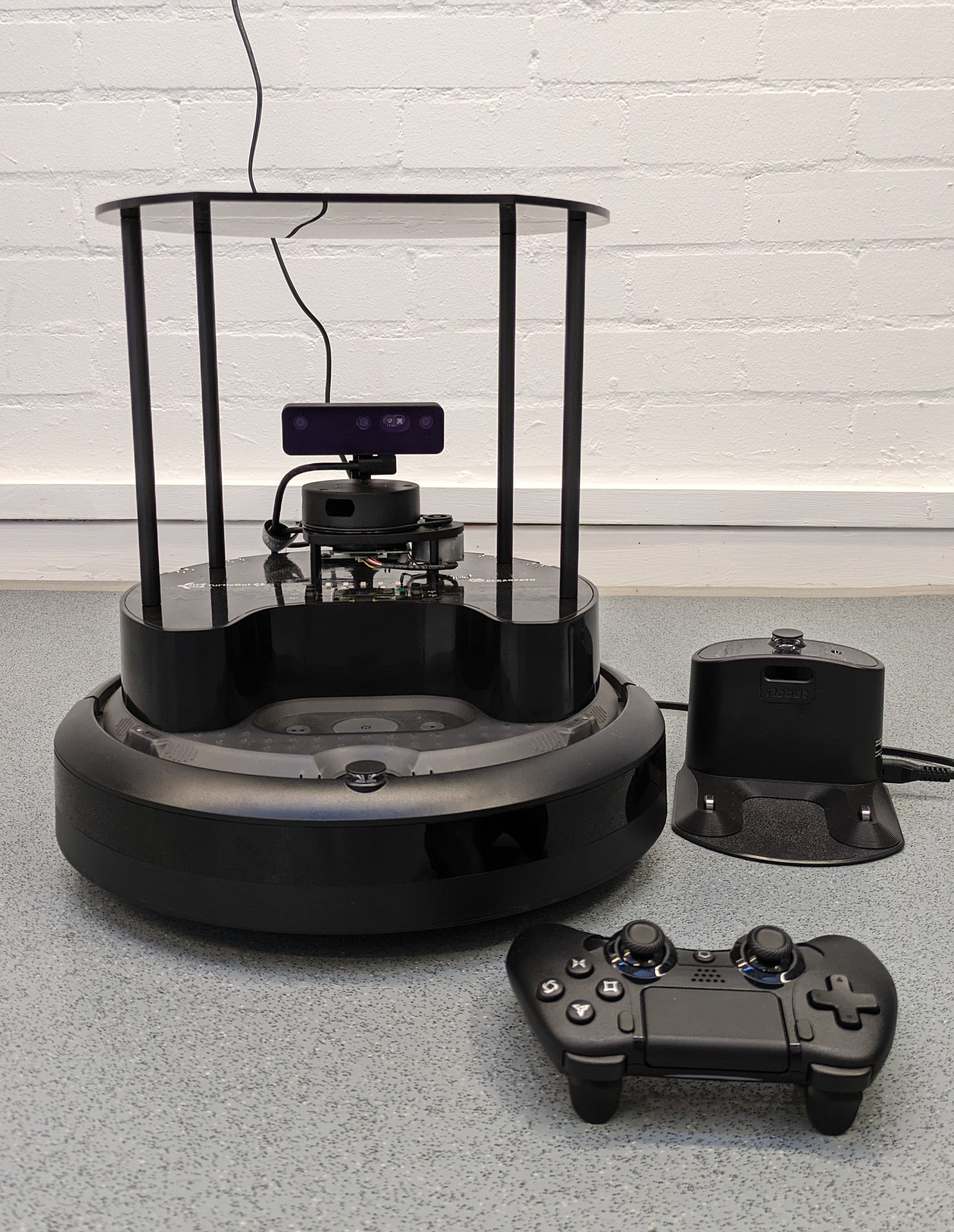
What can it do?
With the onboard OAK-D pro camera and RPLIDAR A1M8 laser range scanner, the Turtlebot 4 is capable of operations such as:
- Mapping and Localization
- Path Planning
- Autonomous Navigation
- Object Recognition
Since this is a robotics platoform, you can intergrate your own sensor payloards or even a small robotic arm on it and conduct even more interesting applications with it.
Getting ready to use Turtlebot 4
As of writing this documentation (02/02/2024), the Turtlebot primarily supports ROS2 Humble, therefore please ensure that you have it installed within your system.
User PC setup
To get your PC/Laptop setup to work with the Turtlebot, please follow the instructions found here
Demos/Tutorials
Additional Resources
- Turtlebot 4 User Manual - click here
- Turtlebot github page - click here
- Documentation for iRobot Create 3 - click here
Using Pololu 3pi+ 32U4 OLED Robot
What is it?
The 3pi+ 32U4 (standard edition) by Pololu is an ATmega32U4 micrcontroller based programmable mobile robot. The micrcontroller powering this robot is the same one that is present in an Arduino Leonardo and Arduino Micro. To find out more about this robot, click here
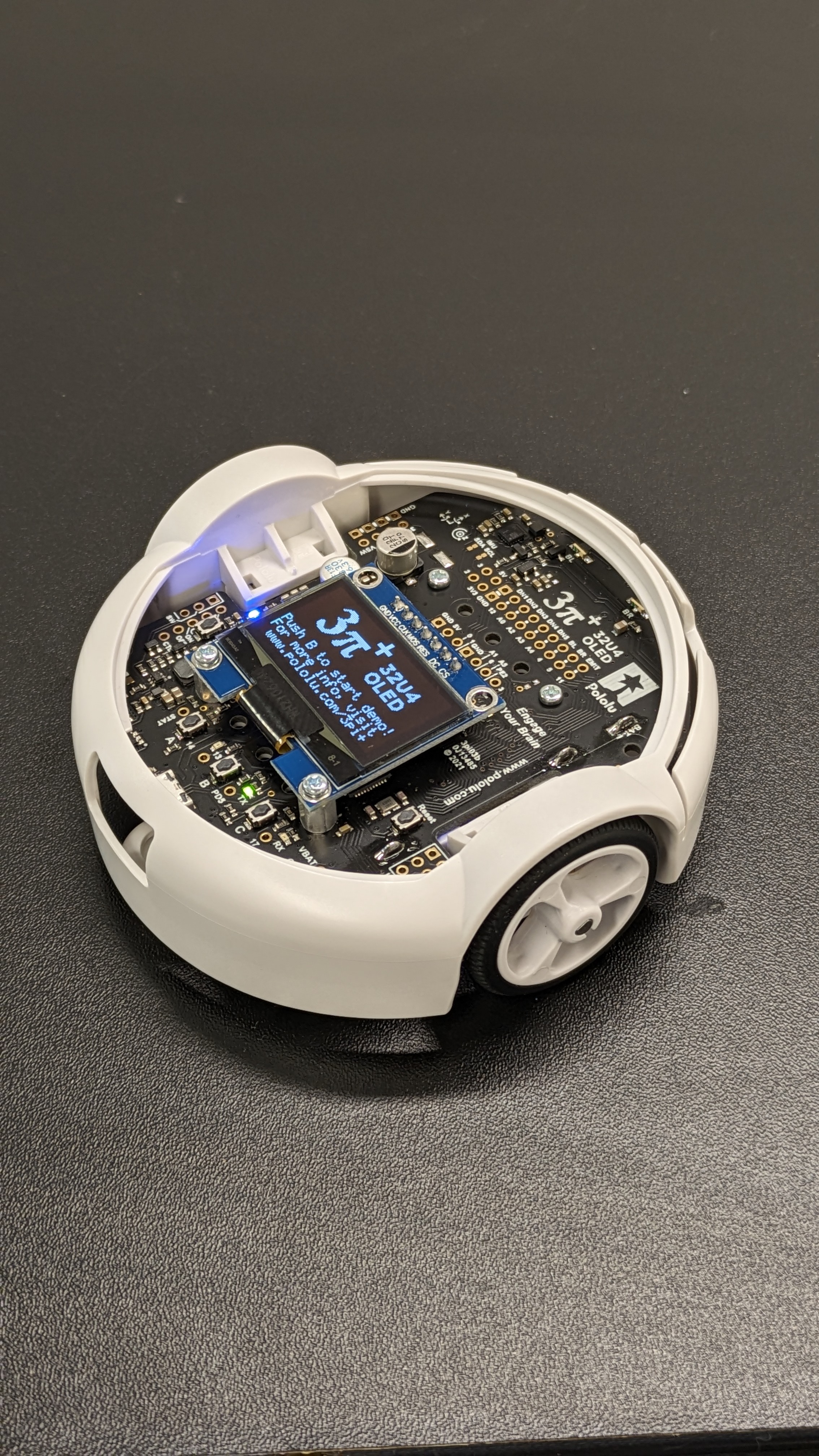
What can it do?
With an assortment of sensors onboard it is capable of applications such as:
- Line following
- Maze solving
- Crash detection
- Simple navigation
Based on how you program it, it can do so much more! Also, check out the preloaded demo programs within the robot.
Programming the 3pi+ 32U4 using the Arduino IDE
To start programming this robot, please refer to the documentation that is given here
Additional Resources
Using Go1 Edu robot dog by Unitree
Safety guidelines
Important: This robot requires an induction before you use it for the first time. If you have not completed this induction, please contact Rohit Ramesh Thampy on Slack
- Users must be 18 or over to use this robot.
- Always ensure to follow the risk assessment for the robot.
- Please keep a distance of at least 1m from people and obstacles.
- If you want to use this robot anywhere else other than the locations mentioned within the risk assessment of the robot, please contact Rohit Ramesh Thampy on Slack or Outlook.
- Do not use this robot on stairs, it can only work on stairs that are 10cm in height, which are quite rare.
- Do not use this robot when the robot's or the remote controller's battery is at 1 bar.
- Ensure to charge the robot's battery and the remote control to its full capacity before using it.
- If you are not confident in using this robot after the induction or need a refresher on using it, please contact Rohit Ramesh Thampy on Slack or Outlook.
- Users of this robot dog is expected to return it in the same state as it was, when it was booked.
What is it?
The Go1 Edu robot dog (otherwise known as a quadruped) is an agile, 4 legged robotic platform.
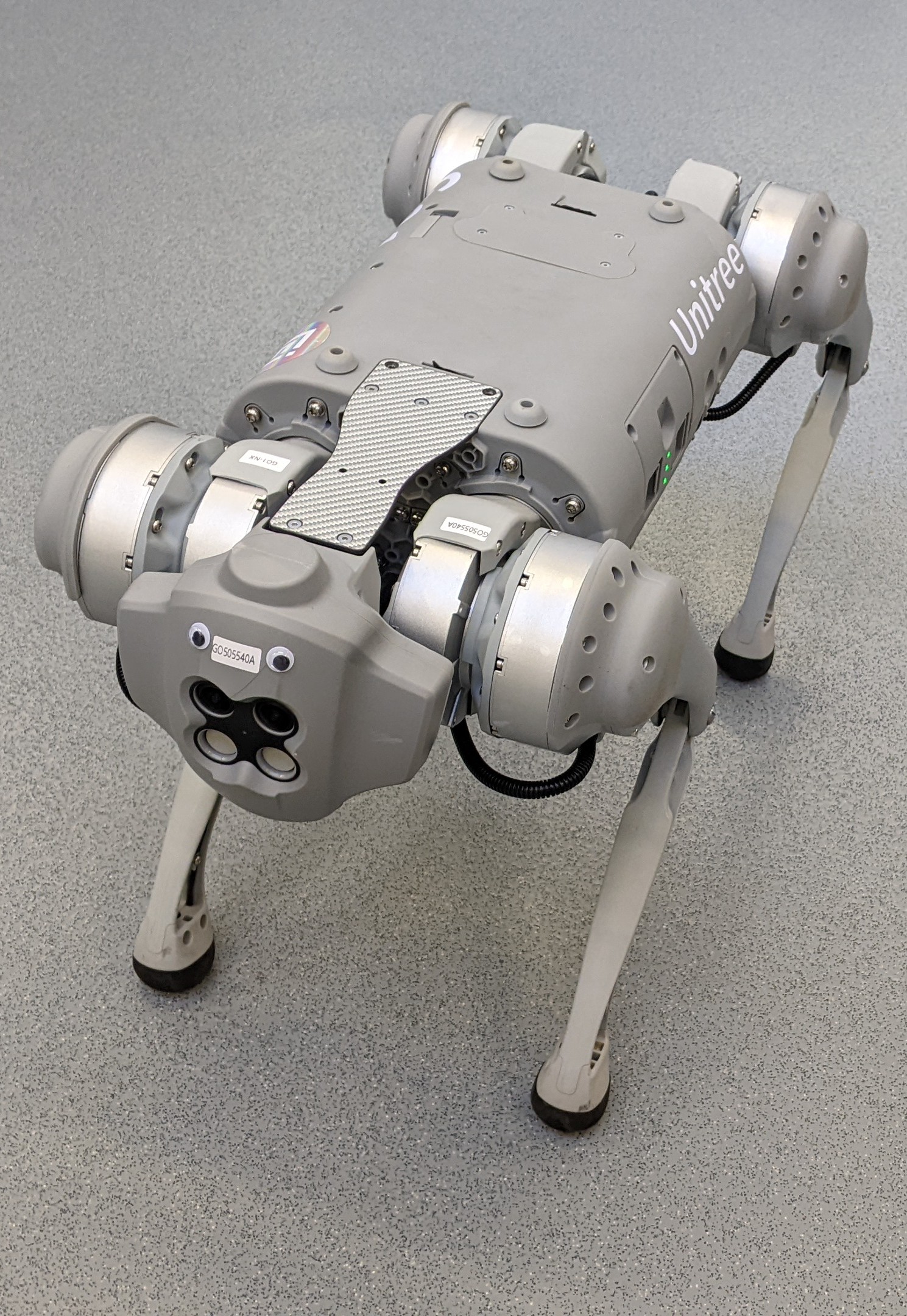
What can it do?
Since it is a legged robot, the Go1 comes with some sophesticated control algorithms built-in, that allows it to balance itself and walk around.
Without any modifications, the Go1 robot dog is capable of doing basic collision avoidance using its onboard stereo cameras. This version also comes with a 2D Lidar, and when that is attached to the robot, it is cabable of doing autonomous navigation.
Since this is a robotic platform, other sensor payloads or hardware can be interfaced with it to extend its capability.
Getting started
Notice: The startup and shutdown procedures for the Go1 are covered in more detail in the induction, therefore please ensure to book and attend the induction before using this robot.
Starting up
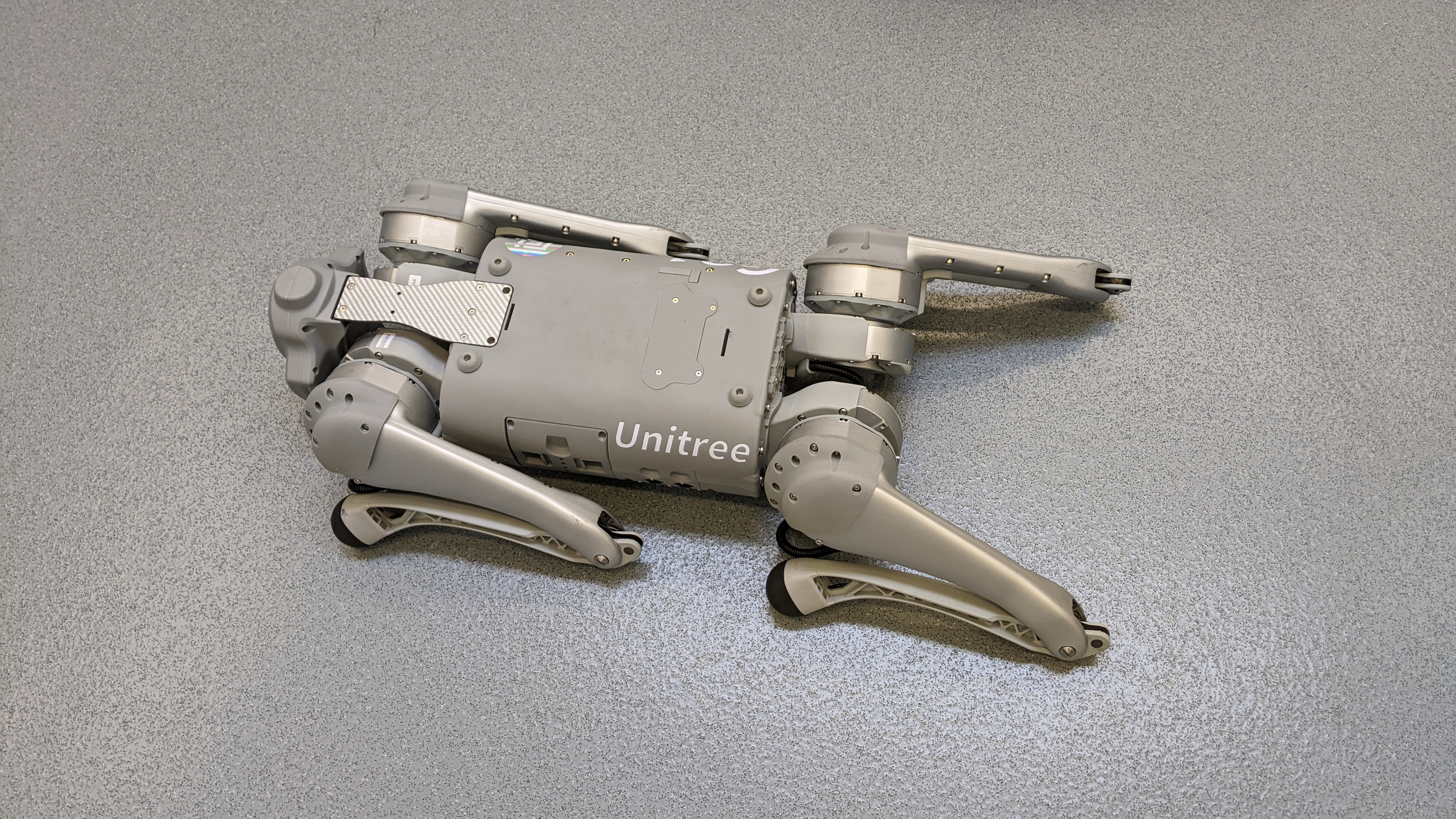
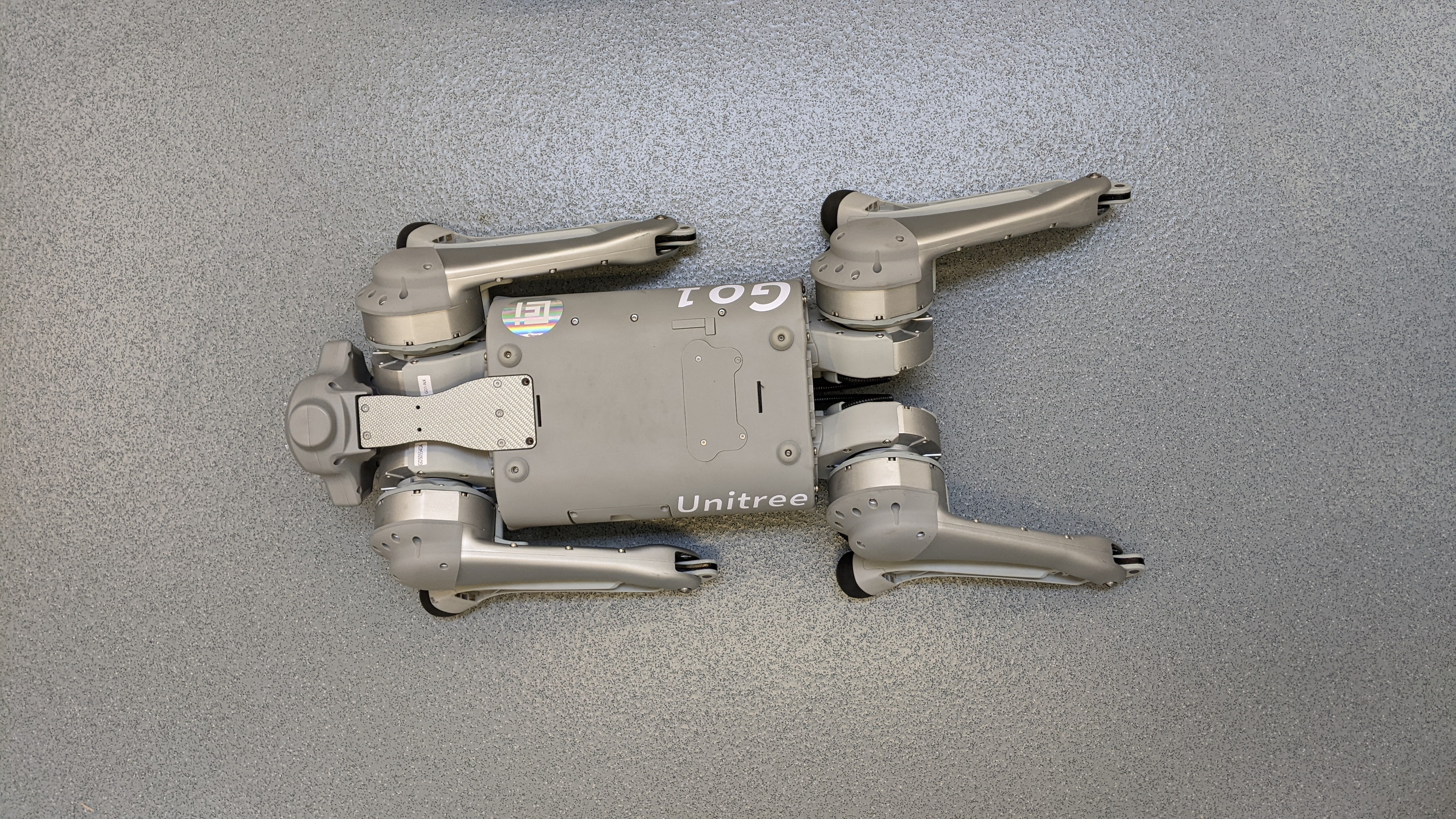
Ensure that the Go1 is placed on a flat and level surface. The robot's abdominal support pad should be flat on the ground and the body should not be tilted. The robot's startup position should look like the images below.
Power on
-
Power on remote control: To do this double click the power button, but on the second click hold down the power button for about 5 seconds or until you hear a beep-beep.
-
Power on robot dog: Power on the robot dog by double clicking on the power button of the robot dog but again hold it down until you see the green LED lights turn on and off. After a couple of minutes, you should see it stand up.
Shutting down
Ensure that the robot is standing still. If it is in motion, bring it to a stop.
Once the robot is standing still press and hold the L2 button. While holding the L2 button, press down on the A button twice and then press down on the B button. Now you can let go of the L2 button.
The short version of this instruction is HOLD L2 + A + A + B RELEASE L2.
The robot dog should now be laying on the floor similar to the starting position.
Power off
-
Power off the robot dog: You can power off the robot dog by double clicking on the power button of the robot dog but hold it down until you see the green LED lights turn off.
-
Power off the remote control: To do this double click the power button, but on the second click hold down the power button for about 5 seconds or until you hear a beep-beep
Controlling Go1
The Go1 can be controlled using the remote control that comes with it, through its SDK and using ROS. However, this document will only cover the remote control aspect.
Basic controls using the remote control
Controlling the Go1 using its remote control is covered in more detail in the induction, therefore please ensure to book and attend the induction before using this robot.
- Left stick - Controls the position of the robot, as in you can move it forward, backward, left and right.
- Right stick - Controls the orientation of the robot, as in yaw, pitch and roll.
All other controls and combinations of controls can be found on the remote controller.
Additional Resources
Using NAO V6
Broken: NAO V6 is currently not functional due to unknown boot issues.
Usage Guidelines
- Please read NAO's pocket guide before using the robot. This can be found in the box with NAO.
- Be careful when picking up NAO, do not place your hands and fingers near the joints or between the limbs as you could be pinched
- Do not pull NAO by the head, arms or legs as that might damage the joints.
- NAO's fingers are fragile. do not pull on them as they might come off.
- NAO is designed for indoor use only.
- Keep NAO away from radiators, open flames and heat sources.
- Do not expose NAO to dust, sand and moisture.
- NAO is not a doll, therefore do not put any kind of clothing accessory, makeup or paint on the robot.
- Never cover the head, in particular the air vent at the back of the robot's head.
- Do not work with NAO on elevated surfaces such as table tops and stairs. If it falls from a height, it will break as it is only capable of withstanding falls from its own height.
- When working with NAO, make sure it is used on a flat surface and provide enough space for it to move around.
- Do not touch or move NAO when it is booting up as this could cause errors.
- Do not use NAO on a rug or thick carpet, as it might fall.
- Please ensure to repack NAO into its box after use.
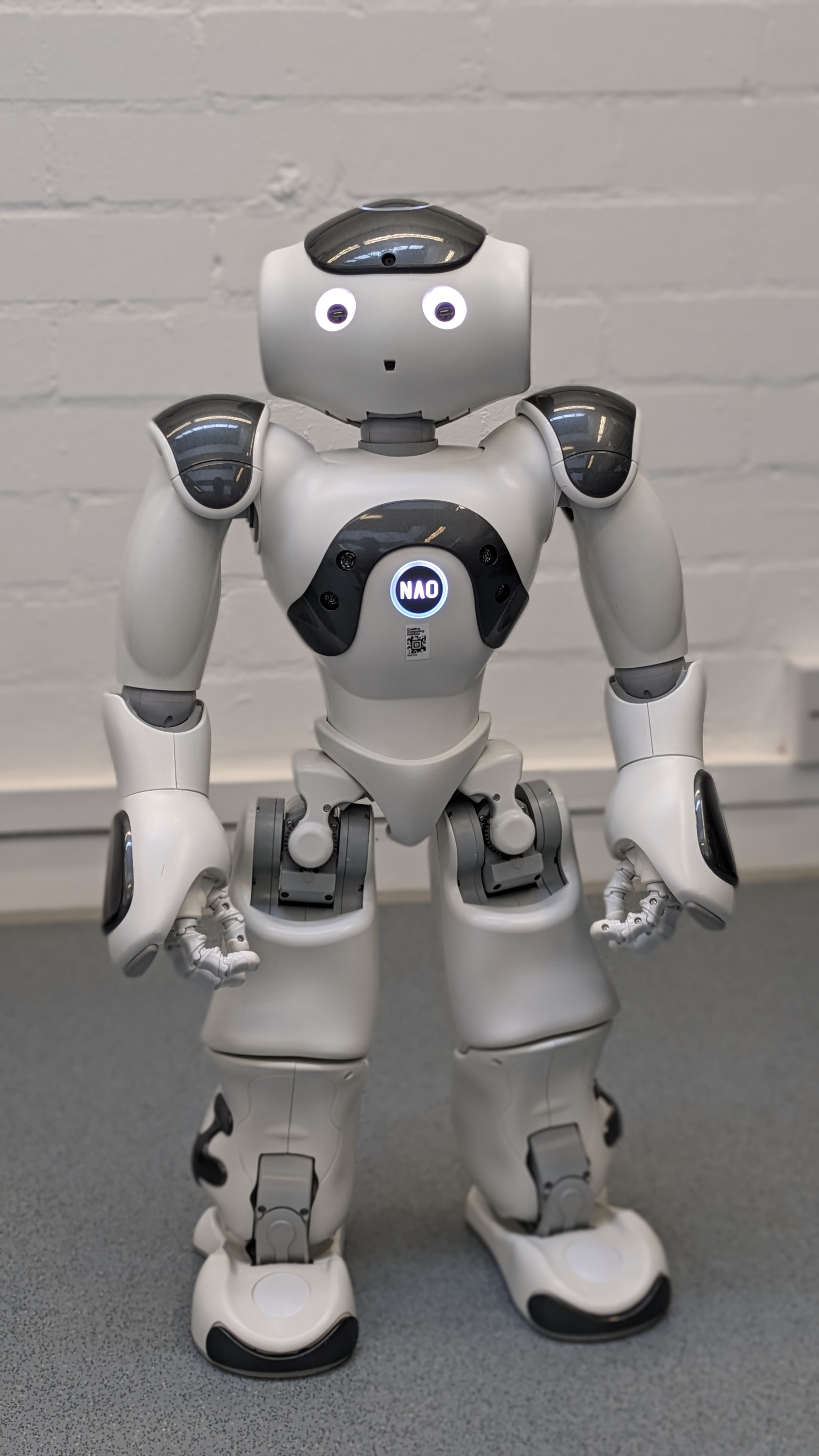
What is it?
NAO (V6) is the latest iteration of the NAO robot series. It is a humanoid robot that provides a blend of interactive features, mobility, and programmability that makes it a versatile tool for education, research, and entertainment. It is equipped with a variety of sensors, motors, and a sophisticated software platform that supports a wide array of functionalities and applications.
What can it do?
- Interact with people: It is equipped with voice recognition and speech synthesis capabilities, which enables it to engage in conversations, respond to questions, and execute voice commands.
- Recognize Faces and Objects: Thanks to its cameras, NAO can identify individuals and objects, allowing for personalised interactions and the ability to navigate most environments intelligently.
- Perform Physical Tasks: With articulated limbs and precise motor control, it can walk, dance, gesture, and even play Football, showcasing its physical capabilities.
- Teach Programming and Robotics: NAO is widely used as an educational tool, helping students learn coding, robotics principles, and AI through hands-on experience.
- Assist in Research: Researchers utilize NAO for experiments in human-robot interaction, cognitive computing, and more, benefiting from its advanced features to test theories and models.Assist in Research: Researchers utilize NAO V6 for experiments in human-robot interaction, cognitive computing, and more, benefiting from its advanced features to test theories and models.
- Provide Entertainment: With its ability to perform and interact, NAO is also used in events and performances, entertaining audiences with its movements and responses.
Getting started
Unpacking and Reboxing
To learn how to unpack and rebox Nao, click here
Software requirements
You will need to download the following software to configure and programe NAO.
- Robot Settings - This software allows you to configure NAO's settings.
- Choregraphe - This software allows tou to programe NAO.
Try downlaoding and installing the setup version these software, if that doesn't work, try the binaries.
You can find these software here
Power on/off
Power on
To power on the robot, press the Chest button once. The chest button is the big circular button located on the chest of the robot with the text NAO on it. You will see the chest button will start pulsing with a white LED.
The boot process is completed once the robot says "OGNAK GNOUK".
Power off
To power off the robot, make sure it is in a safe position, or it may fall. The safe positions are mentioned in the pocket guide. You could also place a hand on its back to keep it in position.
Press and hold the chest button until it says "GNUK GNUK". The shutdown process is complete when all the LEDS are off.
Disengage NAO's motors
Disengage NAO's motors to:
- pick up NAO
- change its posture
- cool down its motors
To do this, double click the chest button. You will notice, the robot goes to its crouching position. To engage the motors again, simply double click the chest button again.
Connecting to NAO
At the time of writing this documentaiton (27/02/2024), NAO is temporarily configured with Rohit Ramesh Thampy's wifi Hotpot. Therefore, please contact him on Slack or outlook if you'd like to use it.
To connect to NAO through the currently configured wifi hotspot:
-
Connect your laptop/PC to the wifi hotspot.
-
Power on NAO and wait till it is fully booted up.
-
Open Robot Settings, the icon for the app should look like the image below.

-
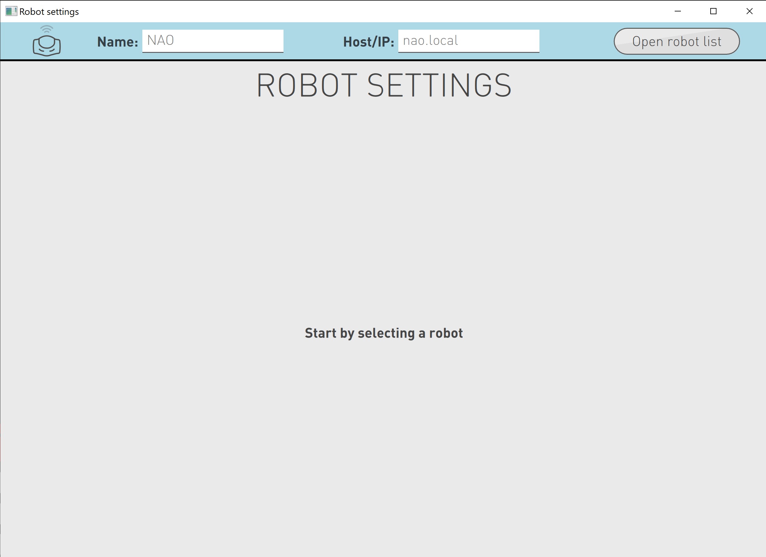
The Robot Settings app looks like the image below.

-
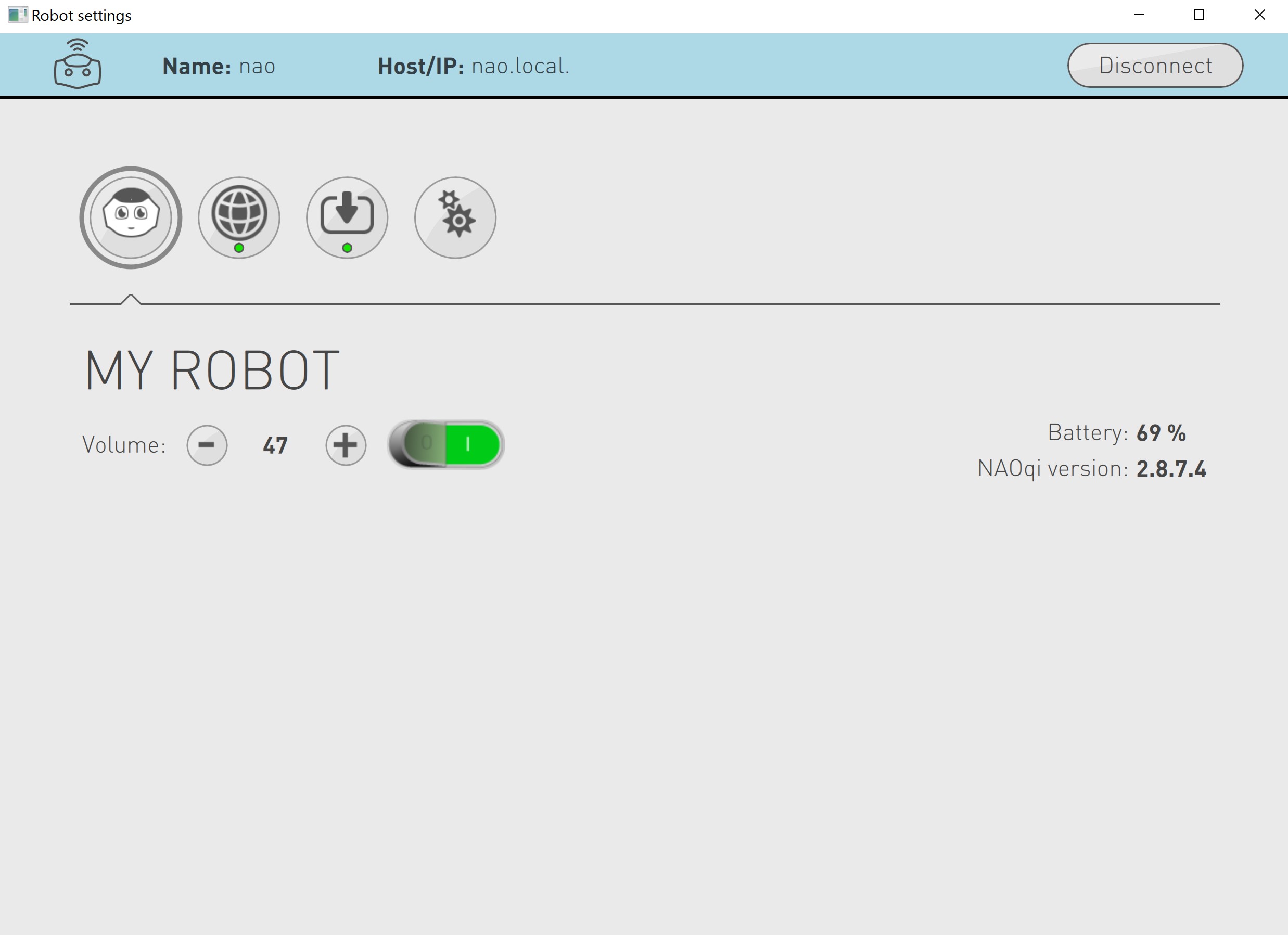
Click on the button that says open robot list, it is located on the top right.
-
This will show you the NAO robots that are available on this network. Click on the one that is available.

-
If everything goes well, you should be connected to NAO and your screen should look like the image below.

-
You should now be able to use this interface to mute, adjust sound and edit other configurations of the robot.

Connect using your own wifi hotspot
Ensure you have atleast 5GB of mobile data on your phone.
To connect NAO to your own wifi hotspot, you will need the following:
- NAO
- A laptop/PC with Robot Settings installed.
- A smartphone with atleast 5GB of mobile data.
- An ethernet cable.
To establish a connection between NAO and your hotspot, read the following:
-
Turn on your wifi hotspot. Instructions for Android devices can be found here. Instruction for Iphone devices can be found here
-
Connect your laptop/PC to your wifi hotspot.
-
Power on NAO.
-
Once NAO is powered on and booted up, disengage the motors by double clicking the chest button.
-
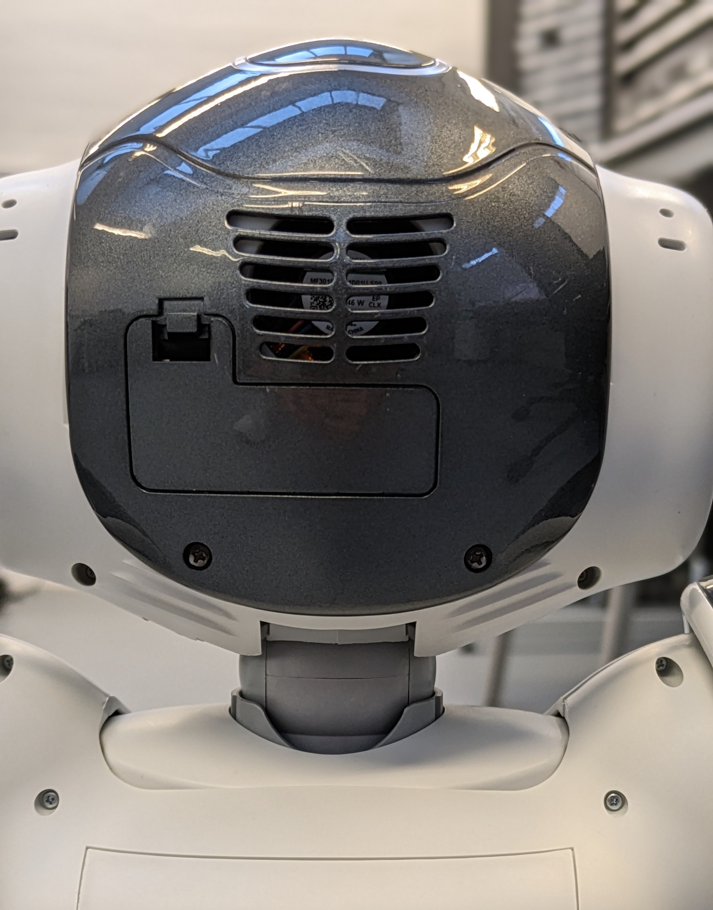
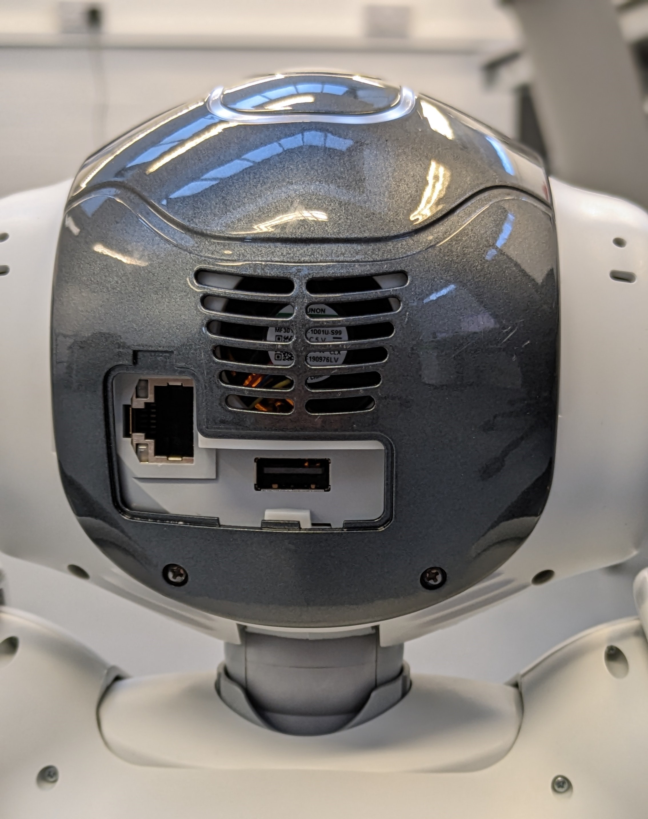
Remove the hatch on the back of the robot's head.


-
Connect one end of the ethernet cable to the ethernet port within NAO's head and connect the other end to your laptop.
-
Wait for about 10 seconds and press the chest button once, this will make NAO say its IP address. Make sure to note it down.
-
If NAO says "cannot connect to a network", wait a bit loger and try the previous step again.
-
Open Robot Settings and enter the IP address next to the text that says Host/IP and press
EnterorReturnon your keyboard. -
If everything goes well, you should be connected to NAO via ethernet and your screen should look like the image below.
-
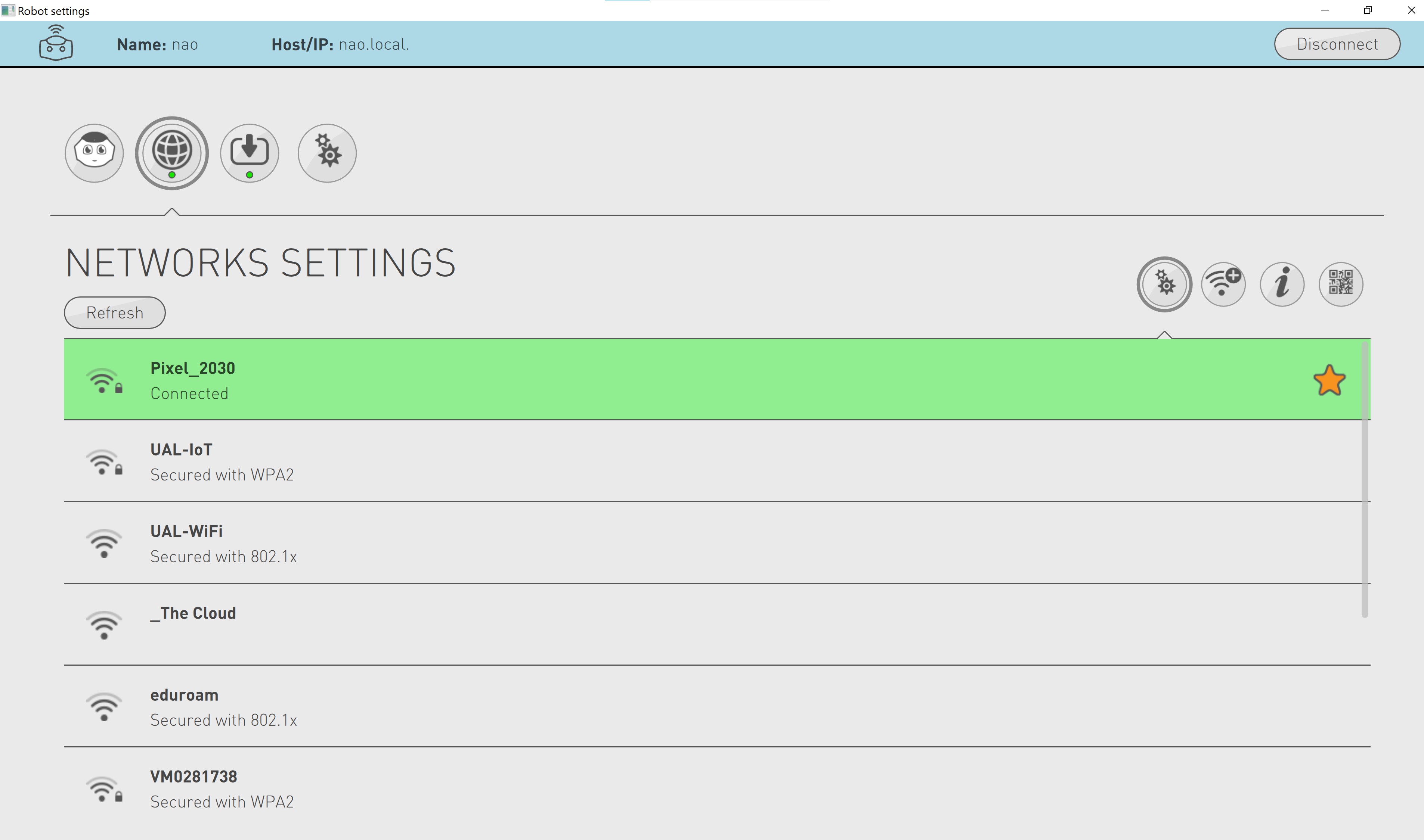
Click on the network icon within Robot Settings, an image of it is shown below.

-
You should now be able to see a list of wireless networks that you can connect to.
-
From this list, select your wifi hotspot and enter its password. Then press enter on your keyboard.

-
Close Robot Settings and remove the ethernet cable from NAO and your machine. Ensure to close NAO's hatch.
-
Reopen Robot Settings and press on NAO's chest button once to get its IP.
-
Enter this IP next to the Host/IP text within Robot Settings and press
EnterorReturnon your keyboard. -
You should now be connected to NAO via your hotspot.
Using Choregraphe to program NAO
Ensure you have connected to NAO through robot settings before attemmpting this.
Make sure to download and install the Choreographer software, which can be found here
-
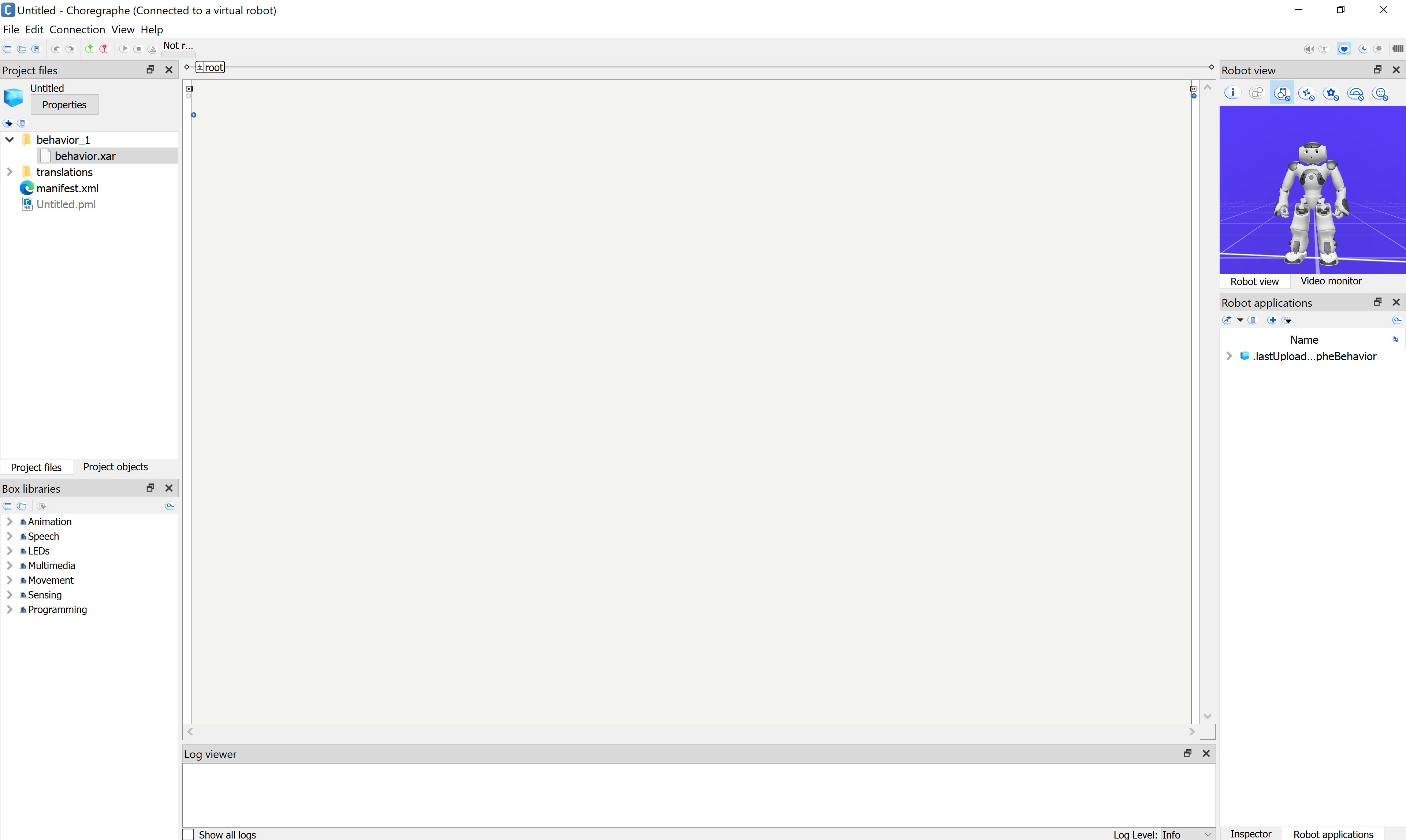
Open Choregraphe, the app's icon will look like the image below.

-
Given below is an image of how it looks like when it is open. Make sure to click
Okon the Getting Started pop up box if that appears.
-
The robot that is shown in Choregraphe is a virtual robot or a simulation. You can change the virtual robot to a NAO by clicking Edit -> Preferences -> Virtual Robot. Click on the drop down list that is next to Robot Model and select NAo H25 (V6). Then click
OK, this will change your virtual robot to NAO. -
Connect to NAO using Choregraphe. To do this click on the
connect tobutton that is located at the top left of the screen. An image of this is given below. You can aslo do connection -> connect to or the keyboard shortcutctrl + shift + corcommand + shift + c
-
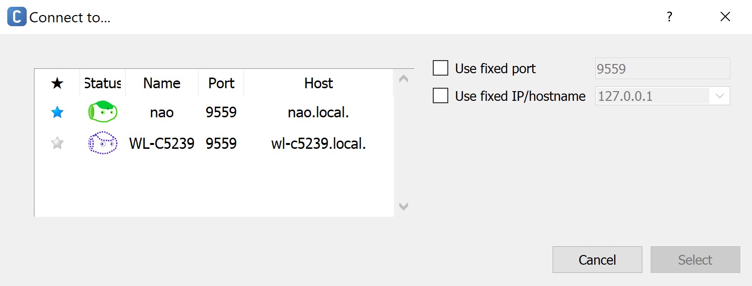
You will notice the following pop up will apprear.

-
On this pop up, click on nao and then click on
select. This should establish a connection between Choregraphe and NAO. -
Try out this "Hello World" tutorial to verify your connection with NAO and to get a feel for programming NAO with Choregraphe.

More Choregraphe with NAO
To learn more about controlling NAO through Choregraphe, click here
Additional Resources
Using mBot2 by makeblock education
What is it?
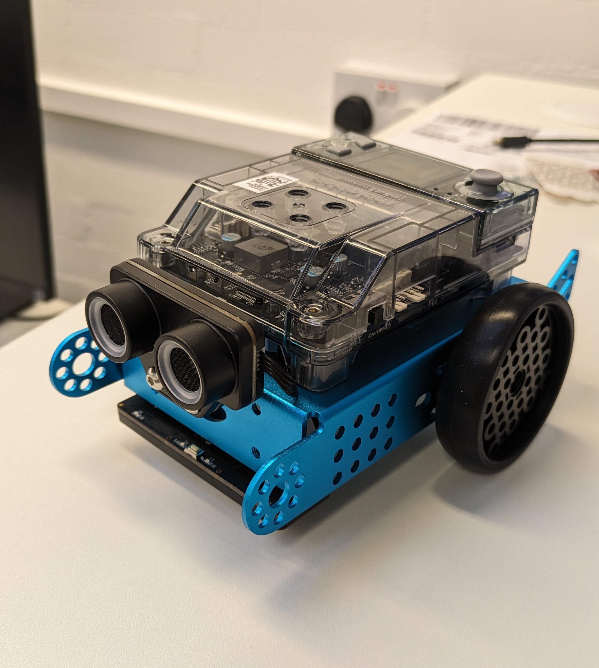
The mBot2 is an education robot designed to teach students about coding and robotics in an engaging and hands-on way.
Getting started
To learn more about mbot2, such as connecting to it and programming it, please refer to the Operation Guide.
Software requirements
mBlock5
The software that is used to control and communicate with mBot2 is called mBlock5. There are two versions of this software.
- PC version - This version runs locally on your machine.
- Web version - This version runs on a web browser cab be found here. However, you will need to download a software called mLink for this method to work.
All the necessary software you need to download can be found here.
mblock-Python Editor
The mBot2 can also be programmed using python. This can be achieved through the python editor present within the mBlock5 software.
If you have the mBlock5 software running locally on your machine, then you can access the python editor by clicking on the python button that is at the top left of your screen.
There's also a web version of the python editor and can be found here. Make sure you also download the mLink software, otherwise, this will not work.
To learn more about using mBlock5 or the python-editor, please refer to the Programming Guide.
Additional Resources
If you need any help with mblock5 or mBot2, please refer to the Help Hub.
Soft Robotics
Specialist information and instruction pages for soft robotics at the CCI.
Intro To Soft Robotics
Soft robotics is a branch of robotics that makes use of compliant (e.g. soft, stretchy, flexible) rather than rigid materials. These kinds of robots are particularly useful in applications involving people and other fragile objects, and they are of particular interest in medical robotics (including surgery, drug delivery and assistive robotics).
Often soft robots are based on biological organisms (which are themselves compliant), and make use of features such as artificial tendons, muscles and blood vessels.
Making Soft Robots at the CCI
Inflatable soft robots
Reference: Inflatable Robotic Project Examples
The classic image of the soft robotic 'tentacle' is made from cast stretchy rubber, with a chamber that guides airflow through a shaped internal structure. As air flows through the chamber, the shape causes the robot to bend in different directions. We stock a range of air pumps, syringes (for manual testing), tubing and valves to test inflatable robots.
For a guide on how to set up an air pump, please see the 5V Air Pump Guide.
Flat/Adhesive Inflatables
Coming Soon: How to make Heat Sealed Inflatables
Adhesive or heat-sealed inflatables have the advantage of being relatively quick to make, and using quite cheap materials.
Cast Inflatables
Workshop: How to make Cast Inflatables
Cast inflatables allow you to make a range of complex 3D shapes, such as grippers and limbs. They can be time-consuming to make, however, so make sure you leave enough time! If you're interested in using the silicone, you need to meet first with Alex and Rohit to discuss your project. We have some example moulds and tentacles in the hack space.
Textile Robots
Workshop: Making a Knitted Actuator
It's also possible to fabricate robotic limbs using the knitting machine, using threads/wires woven into knitted fabric as tendons. CMU's Morphing Matter lab has a project on creating knitted actuators. We've not done much research into this here but want to develop it further, if you're interested come and chat to us.

Auxetic Materials, Origami and Kirigami
Coming Soon: Auxetic Materials Examples
There are a number of ways to change flat, rigid materials into surfaces with a variety of mechanical properties.
Resources
The website Soft Robotics Toolkit was developed as part of an educational initiative by the Harvard Biodesign Lab, and has a huge amount of resources, design guides and learning materials for working with soft robotics. In particular, their OpenSCAD-based design tool
Research
If you're looking for inspiration in developing soft robotics, the following groups are all producing interesting research:
- Whitesides Lab at Harvard University
- Bristol Robotics Lab Soft Robotics Research Group
- Carnegie Mellon University Morphing Matter Lab
- MIT's Self Assembly Lab
- ETH Zurich's Soft Robotics Lab
Soft Robotics Example Projects
CCI Projects
External Projects
Research Papers / Experimental Work
3D Knit for Pneumatic Soft Robots

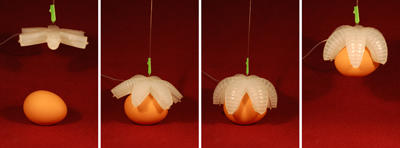
Walking soft-bodied 'starfish' robot from the Whitesides lab.


Machine Knitting Soft Actuated Objects from the Morphing Matter Lab

Bistable Soft Actuator from the Morphing Matter lab, that uses nitinol shape memory alloy to snap between different movement types.


How-to Guides
Artificial Muscle Arm and Gripper


Workshop: How to make Cast Inflatable Soft Robots
The general idea of cast silicone actuators is to create an air pocket that will change the internal shape of the component when the air pressure increases. The shape of this internal section will totally change the behavior of the actuator you are making.
Casting is a great way to make arbitrary shapes of air pockets, and it is a good choice for projects where you need a high level of deformation, or you want to experiment with lots of different shapes.
NOTE: because of the time taken for mould making, it can take around a week to develop a cast silicone actuator. Make sure you are leaving adequate time for your project. Materials are also expensive, and not available to all students by default -- if you're interested in using the silicone, you need to meet first with Alex and Rohit to discuss your project. We have some example moulds and tentacles in the hack space, that can potentially speed up the process.
Process Overview
From start to finish, the process of making a cast silicone mould contains the following steps:
- create or find an existing mould to use
- mix silicone or other elastomer material
- pour initial casts and wait to cure
- seal cured halves of mould and insert tubing
- test and repeat
Materials
We have Ecoflex 00-30 and 00-50 Silicon Cure Rubber in the prototyping lab (00-50 is harder, 00-30 is softer and stretchier). This is a skin-safe silicon rubber that can be cast into 3D-printed moulds. We supply small amounts to students -- you can also source your own from Bentley Advanced Materials It's also possible to make cast inflatables from other materials, such as latex.
Many cast soft robotic actuators also include a layer of paper or fabric to make the actuator stiffer in one direction -- this can be interesting to experiment with, and there are a wide range of materials to try.
Making a Mould
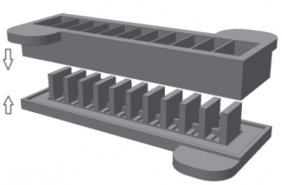
Moulds can be 3d printed, laser cut, or made by hand. In each case, you are trying to make a shaped pocket that will change the shape of the actuator when inflated.
3D Printing Moulds
Advantage Very precise, can make complex shapes, has a good seal
Disadvantage Takes a long time to 3D print, and can be challenging to design! Check whether the mould you want to print already exists
Tools for making 3D printed moulds:
- Guide to the Pneunets bending model, from the Whitesides lab, and another model made using OpenSCAD
- 3D print files and instructions for a 3-arm gripper (note -- ask if a mould exists first before just printing files you've downloaded!)
Laser Cutting Moulds
Advantage Quick to make while still being precise, much easier to design
Disadvantage Requires manual sealing, shapes might be less complex, tend to be much flatter (this can also be an advantage!)
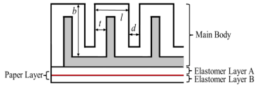
Each part of the mould requires a base plate, and then one or more layers to make up the volume of silicone. In the image below, you can see that one layer has the negative for the air pocket, and then there is a second layer to allow silicone to be poured over the top.
Before silicone is poured into the mould, each layer of the mould should be sealed together with glue to prevent leaking.
- Whitesides lab laser cut soft robotics mould for a leaf-shaped actuator guide

Handmade Moulds
Advantage Doesn't require specialised tools, potential for sculptural/expressive work
Disadvantage Requires manual sealing, shapes might be less precise, more danger of leaks
As in the laser cutting example, moulds should be manually sealed with glue, and should be constructed on a base plate.
Casting Process
At this point, you should have your moulds ready, and have decided which material you want to use, and approximately how much of it you will need. In this example, we will use images from making a two-part mould with Ecoflex 00-50. The 'working time' of ecoflex is around 20 minutes, so once the liquid is mixed, all your moulds must be poured within that time.
If you are a CCI student, you should only be casting in the prototyping lab, and you should first have permission from Alex. You can do this safely at home, but we recommend using the facilities we have here.
- Make sure the workspace is clear and free from dust. Assemble the equipment you need: weighing scale, plastic cup, stirrer, moulds.

- Wear appropriate PPE: Ecoflex is non-toxic, but extremely sticky. Wear nitrile gloves, and an apron.

- Mix the Ecoflex. The casting silicones we stock in the CCI come as mixtures of 2 parts, which must be mixed together in a separate container (e.g. a plastic cup). First, place the cup on the scales and zero the scales. Then pour Ecoflex A to half the total volume that you will require. Take a note of the weight. Zero the scale again, and pour the same weight of Ecoflex B into the container. Mix thoroughly together for 3 minutes.

- Pour the Ecoflex into the mould, making sure to only fill the 'flat' part of the mould halfway (note for more complex moulds this might be different! This is for a simple actuator).

-
To remove air bubbles, either hit the mould on the desk several times (to cause them to pop), or, if available, place the moulds in a vacuum chamber.
-
Leave the moulds to cure for at least 3 hours. Gently demould your designs -- you can use tweezers and/or spudgers to do this, but be careful not to pierce the silicone.
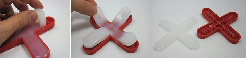
-
Repeat the above steps to make more pourable Ecoflex. Place a piece of paper or fabric (if using) in the the remainder of the flat half of the mould, and then pour a layer of Ecoflex on top. Gently place the section with the air pockets on top of this layer, to seal them together.
-
Wait another 3 hours for the mould to finish curing. Insert a pipe, and seal around the edge.

- Use a syringe, hand pump or 5V air pump to gently test your design (it's best to test with a manual pump first).

(Image Credits: Ben Finio, Science Buddies / Creative Commons Attribution Non-Commercial Share Alike)
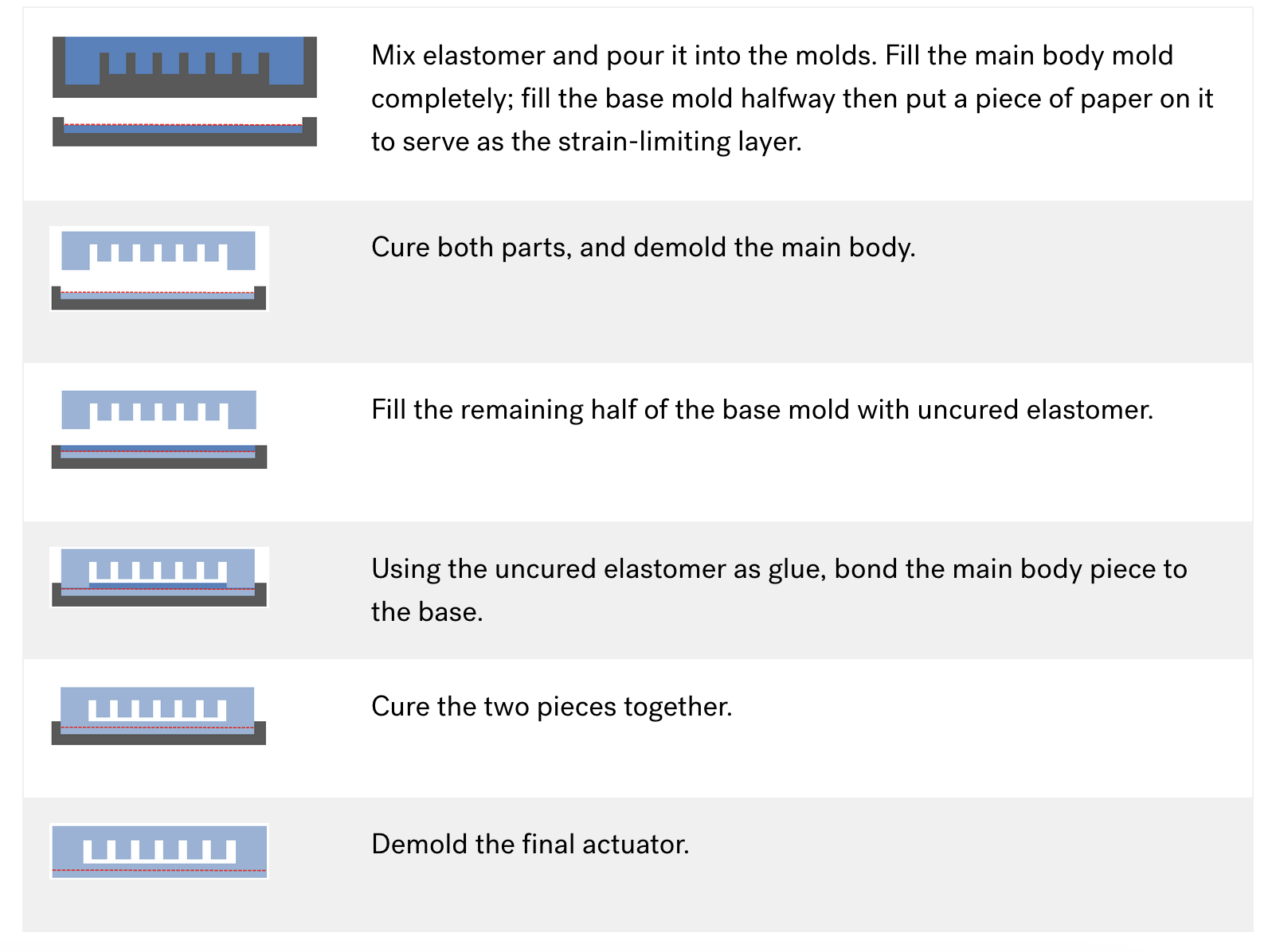
Here are the same steps as a visual guide, from the Whitesides Lab soft robotics guide.
Materials For Soft Robotic Casting
We stock a range of materials for making soft robots, and there are also a number of materials you can source and use at home.
Casting Materials
In general, materials used to make soft robots belong to a family of plastics called elastomers: polymers that will stretch a large amount under stress before returning to their original shape.
Ecoflex

We have Ecoflex 00-30 and 00-50 Silicon Cure Rubber in the prototyping lab (00-50 is harder, 00-30 is softer and stretchier). This is a skin-safe silicon rubber that can be cast into 3D-printed moulds. We supply small amounts to students -- you can also source your own from Bentley Advanced Materials.
Latex
Latex can be used to make flat elastic sheets and cast structures like balloons, with very thin layered structures. It is normally dipped or spread onto a surface rather than cast in a mould. The advantage of latex is that it's very cheap! However -- be mindful that some people have a latex allergy, and be careful when using.
Alginate
Make sludge