🌟 Design the clearance and tolerance
Before exporting your model, make sure it has been designed with 3D printing tolerance in mind.
In this guide, tolerance means designed clearance between printed parts. In other words, it is the small gap you intentionally leave between parts so that they can fit, slide, rotate, or connect properly after printing.
If two parts, for example a peg and a hole, are designed to be exactly the same size, they may become very tight after printing. On the Bambu H2D Pro printers, this can sometimes still work for a very tight fit. However, on the Ultimaker S7 printers, the parts are more likely to be too tight and may not fit at all without sanding or adjustment.
How Tolerance Is Measured
When we say 0.1 mm tolerance, this usually means 0.1 mm clearance on each side.
For example, if a peg is 10 mm wide and you choose a 0.1 mm tolerance, the matching hole should be designed as:
10 mm + 0.1 mm + 0.1 mm = 10.2 mm
So the hole should be 10.2 mm wide, allowing 0.1 mm clearance on each side.
Tip: Tolerance is usually added to both sides of the part.
A 0.1 mm tolerance normally means 0.2 mm total extra space in the hole.
The correct tolerance depends on the printer, material, print orientation, and the type of fit you need.
Bambu H2D Pro Tolerance Guide
Important: These values are starting points, not fixed rules. Always test a small sample first if the fit is important.
The Bambu H2D Pro printers can usually produce tighter and cleaner fits than the Ultimaker S7 printers, but you should still design with clearance.
For the Bambu H2D Pro printers, we usually recommend testing around:
0 mm, 0.1 mm, 0.15 mm, or 0.2 mm
The correct tolerance depends on the type of fit you need.
| Use Case | Suggested Tolerance | Notes |
|---|---|---|
| Very tight fit / press-fit | 0–0.05 mm | Very tight. May need force to assemble. Always test first. |
| Peg and hole for alignment or basic assembly | 0.1–0.15 mm | Good for parts that need to locate or align without too much wobble. |
| General removable parts | 0.15–0.2 mm | Good for parts that need to be assembled and removed by hand. |
| Joints, hinges, or sliding parts | 0.15–0.2 mm | Leave enough clearance so the parts can move after printing. |
| Free movement / large contact areas | 0.2 mm+ | Use for rotation, sliding, repeated removal, or larger contact areas. |
| Interlocking parts | Depends on contact area | Avoid making the fit too tight, especially for large contact areas. |
Note: Sometimes, even on the Bambu printers, 0 mm tolerance can still be too tight. The final fit can be affected by material, print orientation, first-layer squish, wall thickness, and the shape of the part.
Bambu H2D Pro Screw Hole Guidance
For screw holes on the Bambu H2D Pro printers, the tolerance depends on the fixing method.
| Fixing Method | Suggested Approach | Notes |
|---|---|---|
| Screw bites directly into printed plastic | Use -0.2 mm, -0.1 mm, or 0 mm | The hole is slightly smaller so the screw can grip the plastic. |
| Screw tightened with screwdriver | Use -0.1 mm or 0 mm | Depends on screw type and how strong the fixing needs to be. |
| Hand-tightened screw | Use 0 mm or slightly loose | Useful when the screw needs to be removed easily. |
| Brass threaded insert | Use the insert outer diameter and manufacturer’s recommended hole size | Do not use the screw diameter. Always test first. |
If the screw is meant to bite directly into the printed plastic, the hole is usually designed slightly smaller than the screw diameter. This is why you may use a negative tolerance.
For example, if the screw diameter is 3 mm and you use -0.1 mm tolerance, the hole diameter would be:
3 mm - 0.1 mm = 2.9 mm
This gives the screw some material to grip into.
Important: If you are using brass threaded inserts, do not design the hole based on the screw diameter.
The hole size should be based on the outer diameter of the brass insert and the manufacturer’s recommended hole size.
Always test with a small sample first.
Ultimaker S7 Tolerance Guide
Important: These values are starting points, not fixed rules. Always test a small sample first if the fit is important.
The Ultimaker S7 printers usually need more clearance than the Bambu H2D Pro printers.
If you use the same tight tolerance as Bambu, the parts may become stuck or may not fit after printing.
For the Ultimaker S7 printers, we usually recommend starting from 0.2 mm per side and increasing the clearance depending on the type of fit.
| Use Case | Suggested Tolerance | Notes |
|---|---|---|
| Very tight fit / press-fit | 0.2 mm per side | Safer starting point on Ultimaker. |
| Peg and hole for alignment or basic assembly | 0.2 mm per side | Safer starting point for general assembly. |
| General removable parts | 0.3 mm per side | More reliable for parts that need to be taken apart. |
| Joints, hinges, or sliding parts | 0.3 mm+ per side | Use more clearance if the part needs to move freely. |
| Free movement / large contact areas | 0.4 mm+ per side | Use for rotation, sliding, repeated removal, or large contact areas. |
| Interlocking parts | Depends on contact area | Avoid making the fit too tight, especially for large contact areas. |
For example, if a peg is 10 mm wide and you use 0.2 mm tolerance per side, the matching hole should be:
10 mm + 0.2 mm + 0.2 mm = 10.4 mm
So the hole should be 10.4 mm wide, or even 10.45 / 10.5 mm.
Warning: On the Ultimaker S7, using the same tight tolerance as Bambu will cause parts to become stuck or not fit at all.
Ultimaker S7 Screw Hole Guidance
For screw holes on the Ultimaker S7 printers, the tolerance depends on the fixing method.
| Fixing Method | Suggested Approach | Notes |
|---|---|---|
| e.g RS PRO Brass Threaded Insert, 4.6 mm diameter 4 mm 5.7 mm | Use -0.1 mm, 0 mm | The hole may to be slightly smaller than the screw diameter. |
| Screw tightened with screwdriver | Use 0 mm or 0.1 mm | Depends on screw type, material, and required strength. |
| Hand-tightened screw | 0.1 mm | Useful when the screw needs to be removed easily. |
| Brass threaded insert | Use the insert outer diameter and manufacturer’s recommended hole size | Do not use the screw diameter. Always test first. |
If the screw is meant to cut into or bite directly into the printed plastic, the hole may need to be slightly smaller than the screw diameter.
For example, if the screw diameter is 3 mm and you use -0.1 mm tolerance, the hole diameter would be:
3 mm - 0.1 mm = 2.9 mm
This gives the screw some material to grip into.
Important: If you are using brass threaded inserts, do not design the hole based on the screw diameter.
The hole size should be based on the outer diameter of the brass insert and the manufacturer’s recommended hole size.
Always test with a small sample first.
Things That Can Affect Tolerance
Tolerance is not fixed. It can change depending on:
- Material
- Print orientation
- Wall thickness
- Print speed
- Nozzle size
- First-layer squish
- The size and shape of the object
- Contact area between parts
- Whether the part needs to move or stay fixed
- Whether the part will be assembled once or repeatedly removed
Tip: Always test a small sample first when the fit is important.
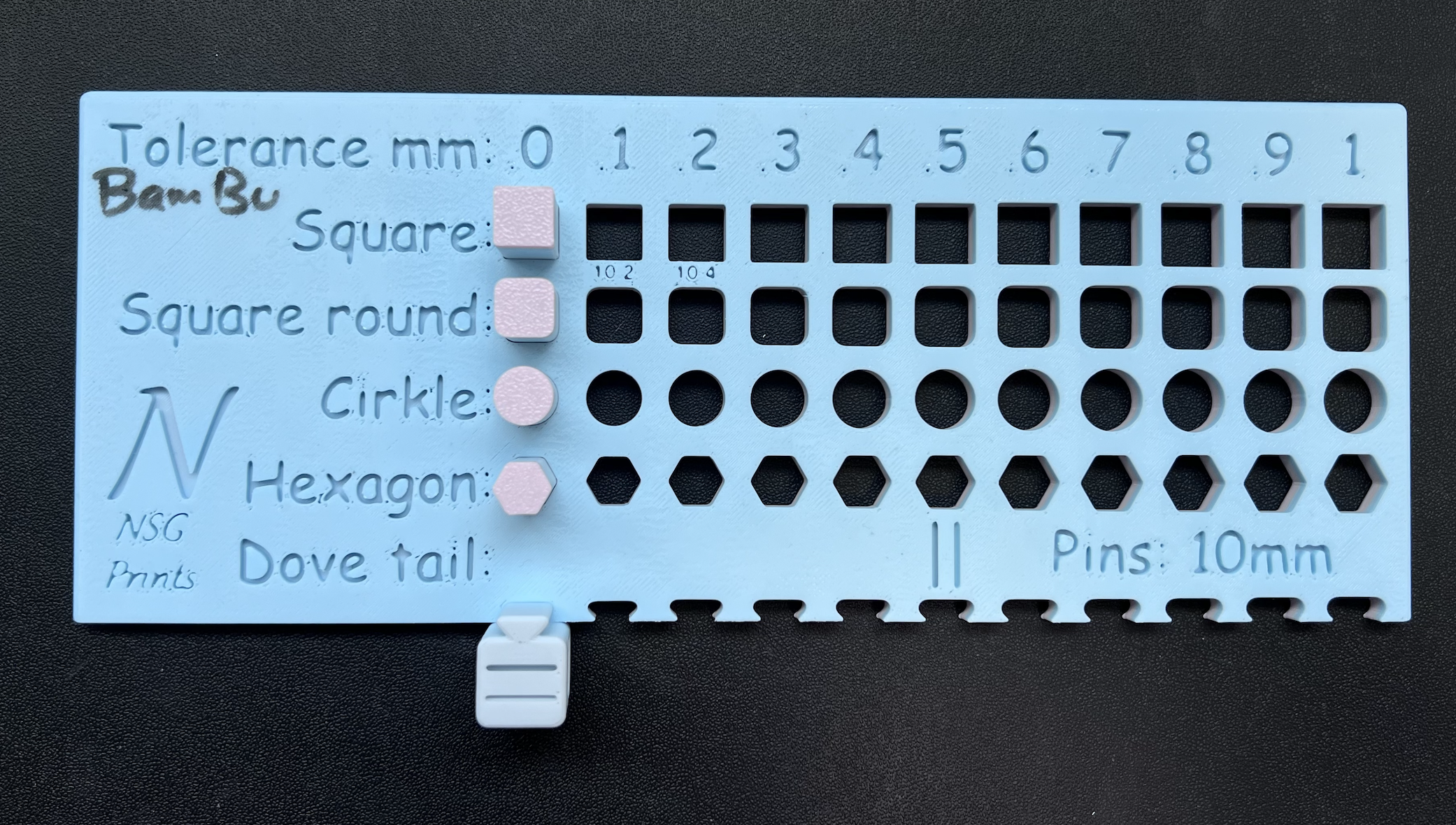
You can also check the tolerance sample board in the lab before printing the full object.