
Knitted Stretch Sensors
Knitted fabrics that integrate conductive yarn will have different amounts of resistance, depending on the size of the sample, the density of the stitches, and the yarns used. Yarns that are partially made up of metal have the unique property that their resistance changes under tension. This happens as the metal fibres in the yarn are pulled together, meaning that the current is able to flow more easily. This essentially creates a variable resistor which can then be used as a stretch sensor.
In the circuit below, the knitted stretch sensor is being used to control the brightness of an LED:
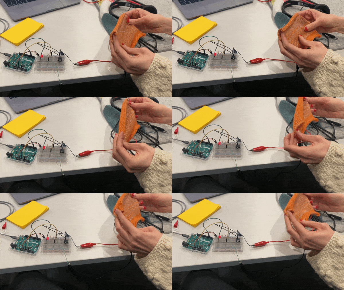
These sensors can be used anywhere a potentiometer would be used instead. Typically the signal is much noisier and harder to control, but you can still get some interesting results! One example project is the knitted synthesisers workshop.
Measuring Change in Resistance with a Voltage Divider
We can't directly measure resistance with an Arduino but we can use a circuit called a voltage divider to measure a specific voltage which we can then use to calculate resistance. Below is the circuit diagram for a voltage divider where R2 is the resistor we are trying to measure and R1 is a resistor of fixed value that we must choose (more on this later).
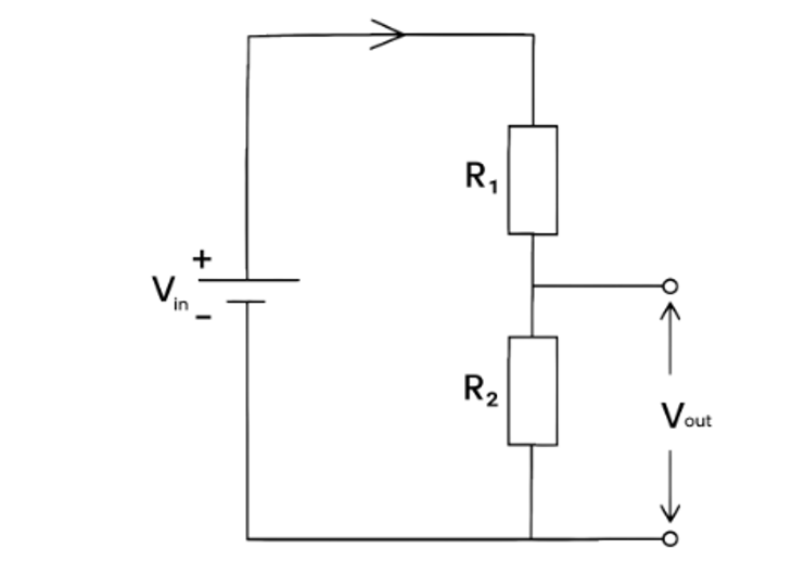
A voltage divider divides up the input voltage, Vin, proportional to the values of the two resistors, R1 and R2. You can essentially think of it as the resistors sharing the voltage out between the two of them according to their value. The higher the value of the resistor, the bigger the share of the voltage it gets.
If we know both resistor values, we can calculate Vout using the voltage divider equation below:
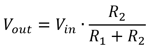
However, if we are trying to find R2 then we can instead measure Vout and use this to calculate R2.
Example
If we have a circuit with Vin=5V, R1=10kΩ, and R2=10kΩ, then the input voltage would be split in half, giving us Vout=2.5V.
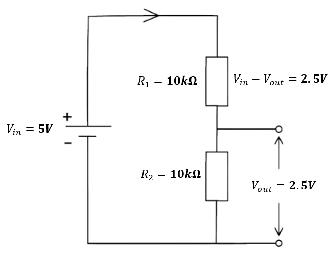
However, if we have a circuit where R1=20kΩ is much greater than R2=1kΩ then the larger R1 gets most of the voltage and we are left with Vout=0.2V.
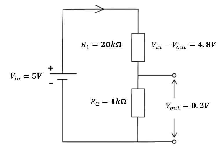
We can then calculate the value of R2 as we know the values of R1, Vin, and Vout.
Voltage Dividers and Arduino
In this instance, the purpose of using a voltage divider is not to find the exact value of R2, but to measure a changing resistance. Therefore, we don't actually need to do any of these calcuations, we can simply measure the value of Vout and use this as the sensor value as it will vary with the value of R2.
To create a voltage divider with an Arduino, we will need to connect the two resistor together in series between 5V and GND then connect the point between them to an analog pin on the Arduino. Make sure that the variable resistor (e.g. a conductive knit swatch) is in the R2 position as this is the one we want to measure.

#define sensorPin A0

void setup() {
  pinMode(sensorPin, INPUT);
}

void loop() {
  int val = analogRead(sensorPin);
}
Choosing R1
If you are using a voltage divider to measure the value of R2, the specific value of R1 is arbitrary, as long as it is known. However, if we want to create a sensor using a knitted swatch, the value of R1 will effect the sensitivity of that sensor.
For example, let's say we have Vin=5 and a variable resistor, R2, that varies between Rmin=1k and Rmax=10kΩ.
First lets try the value of R1=20kΩ. Using the voltage divider equation from above we can calculate the values of Vout for the max and min values of R2.
| R2 | Vout | |
|---|---|---|
| Rmin | 1kΩ | 0.2V |
| Rmax | 10kΩ | 1.7V |
This give us a total range of 1.7-0.2 = 1.5V. Now let's try R1=5kΩ
| R2 | Vout | |
|---|---|---|
| Rmin | 1kΩ | 0.8V |
| Rmax | 10kΩ | 3.3V |
This gives us a much better range of 3.3-0.8 = 2.5V.
The larger the range of Vout, the more sensitive the sensor will be. The absolute optimal value is R1 = √ (Rmin Rmax) however, you can also just find the value that is around halfway between Rmin and Rmax.
Measuring Rmin and Rmax
In order to choose R1, we therefore need to know the value of Rmin and Rmax. We can do this by measuring our swatch with a multimeter.
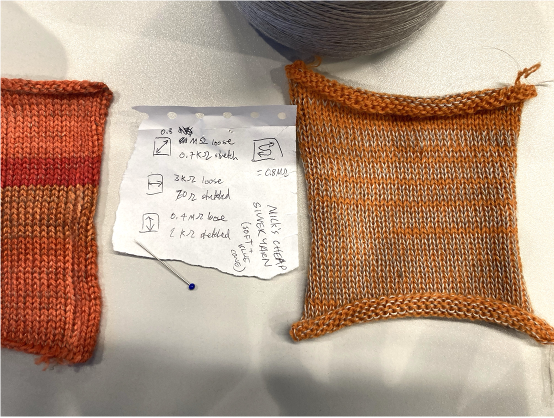
Attach the crocodile clips to the edge of the sample, and connect the other ends to the multimeter. Move the wheel of the multimeter to the setting with the Ω symbol, and press the 'mode' button until you also see a Ω on the screen.
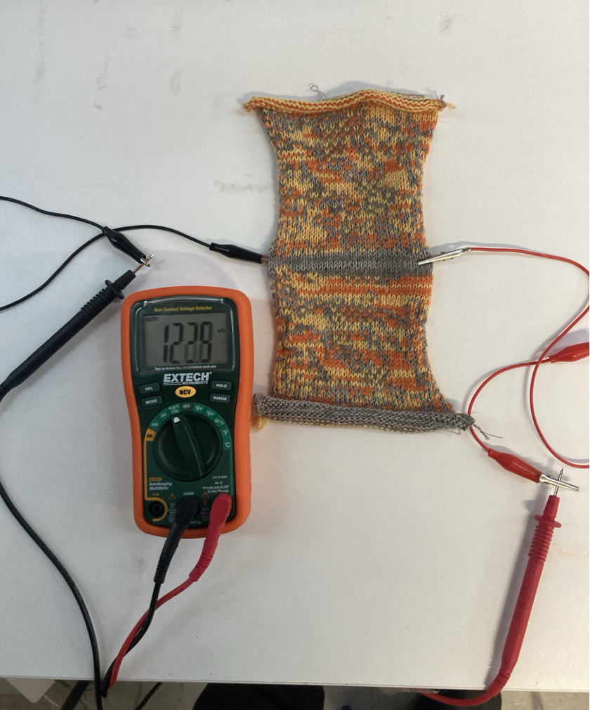
Once the system is connected, you should see a reading of the sample's resistance on the multimeter. Try stretching the sample and the number should decrease! Therefore, the unstretched reading is Rmax and the stretched reading is Rmin. Note that the letters next to Ω refer to the magnitude: k stands for 'kilo' (x1000), and M stands for 'mega' (x 10,000). You want your sample to be at least a few kΩ for the voltage divider to work.
These can then be used to find your value of R1. Don't worry if there isn't a resistor that is the exact value you have calculated! It doesn't need to be exact, just around the right area to give you a good amount on sensitivity.