Connecting a Potentiometer
What is a potentiometer?
A potentiometer (often abbreviated to pot) is an electronic component with three connections, the main purpose of the pot is to create a variable voltage as an input to a circuit, for example controlling how loud your speakers should be.
 ]
]
Inside a potentiometer is a large resistive area between pin #1 and #3, the middle pin #2 is called the wiper, and by actuating the pot you can select a position along that resistive area to create a proportional to the voltage between pins #1 and #3.
For example if you have Ground (0V) on pin #1, and 5V on pin #3, you could select a voltage between 0V to 5V, at the half way the voltage on pin #2 would be 2.5V.
Different types
There are two main types:
Rotary Potenitometer
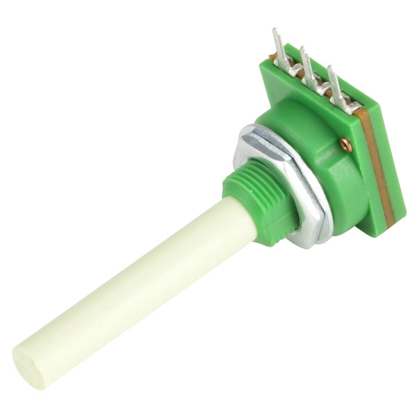
Rotary Potentiometers like those found on speakers to control the volume.
Slide Potentiometer
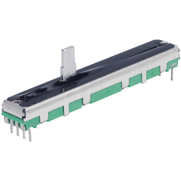
Slide Potentiometer like those found on audio mixing desks.
Wiring
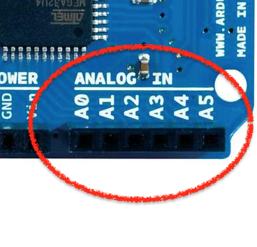
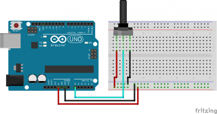
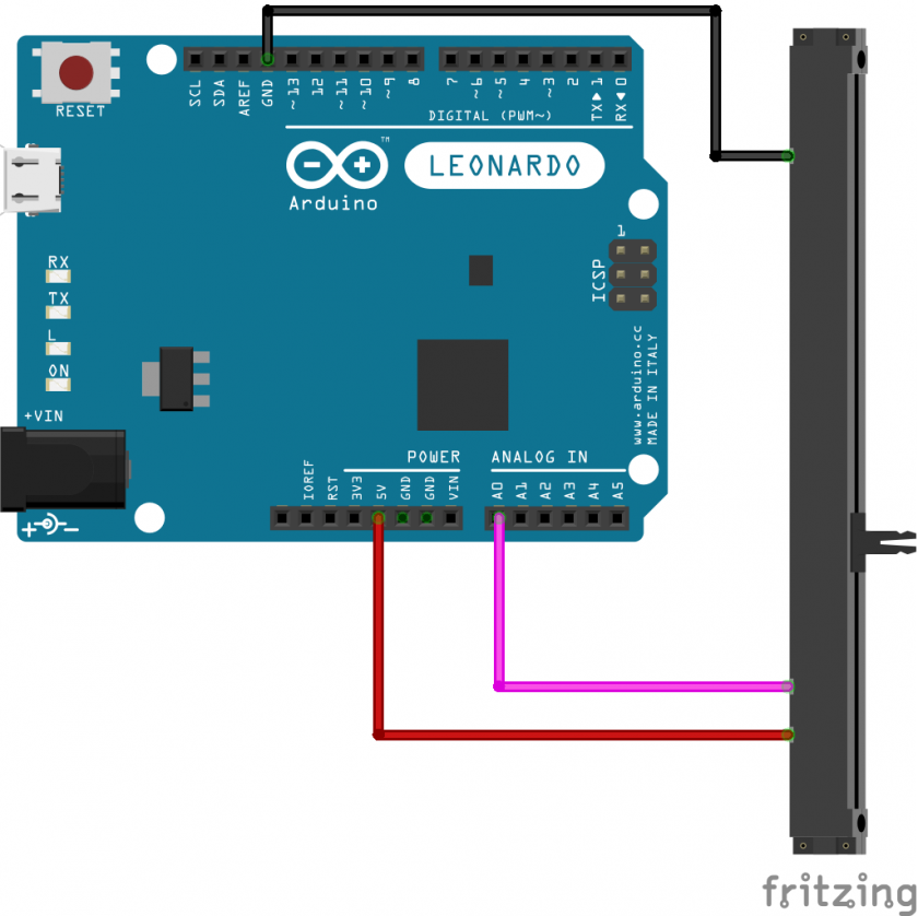
At its most basic, pins #1 and #3 need to be connected to Power and Ground, for example 5V and GND on an Arduino. Pin #2 the wiper needs to be connected to the analog input pins:
Rotary Potentiometer Wiring
Slide Potentiometer Wiring
Identifying the pins of a potentiometer
The most common type of potentiometer to use is a 10KΩ potentiometer, that means the resistance between pin #1 and #3 is fixed at 10KΩ or thereabouts, and that the resistance between pin #2 and either of the other two will be proportional to the position of the potentiometer rotation/sliding.
In other words, using a multimeter set to resistance/ohms/Ω measurement you can find the two pins that don't change at all, and measure a resistance close to the rating marked on it. The remaining leg is likely the wiper.
Getting started
The following is a simple sketch that will get a potentiometer controlling the LED built into the Arduino.
This sketch will make the LED blink at a rate between 0ms to 1023ms, this is because the function analogRead returns a value between 0-1023.
#define ledPin 13
#define potPin A0

void setup() {
  pinMode( ledPin, OUTPUT );
  pinMode( potPin, INPUT );
}

void loop() {
  digitalWrite( ledPin, HIGH );
  delay( analogRead( potPin ) );

  digitalWrite( ledPin, LOW );
  delay( analogRead( potPin ) );
}
