Sending data between TouchDesigner and Arduino
Just like most other creative coding languages and platforms, TouchDesigner allows you to connect an Arduino and hook up sensors, LEDs, servos, etc. to your project.
The makers of TouchDesigner offer a guide about how to do this.
Their article includes sample project files and Arduino code.
Although the sample has some annotations to explain how it works, we will explain a little bit more as it might still be confusing ;)
When you open the 'Arduino_sample.tox', you will be greeted with a screen like here below.
You can use your mouse to rotate/move/zoom the blobby ball, see values coming in from the Arduino, and click on the grey rectangular button to send values back.
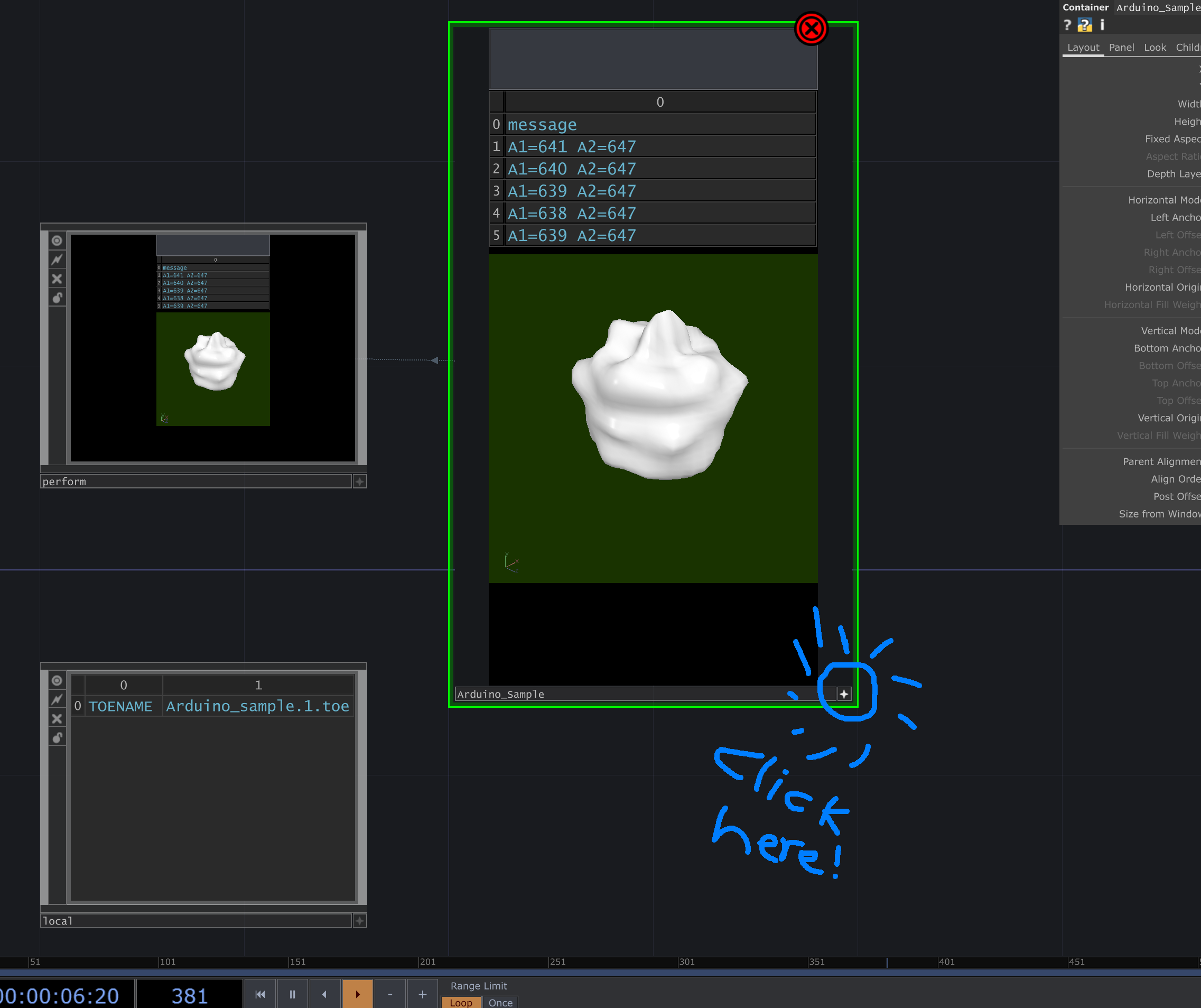
If you click on the little star icon in the bottom right corner of the blobby ball's container panel, it will take it out of interaction mode. You can now zoom all the way in to see the actual sketch inside the container, which looks like this:
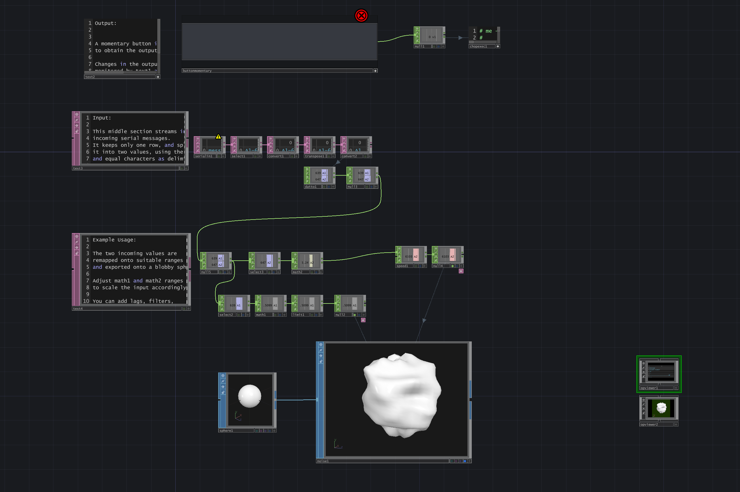
This is where the actual TouchDesigner network is. The top section creates a grey button; if you click it, it will send a command to your Arduino (to turn on/off an LED).
The middle section handles incoming data (messages) from the Arduino. This is what we will focus on here.
The sketch expects that the Arduino sends its messages in a certain format: i.e. "A1=123 A2=456" (see the accompanying Arduino code). Each message represent two analog sensor values, like potentiometers for example.
Let's have a look at how they parse (process) the incoming message!
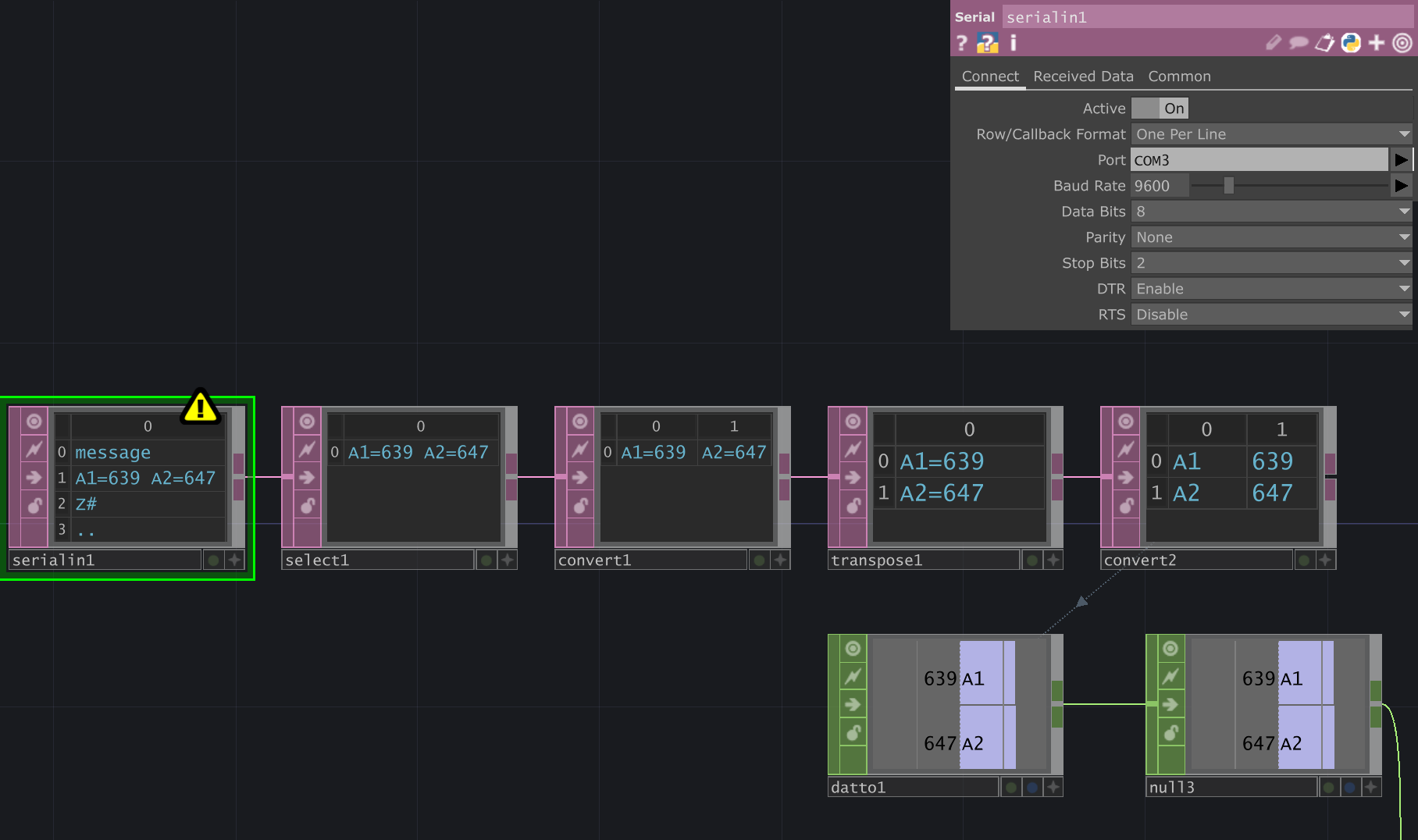
The first box (serialin1) does the serial port communication with the Arduino. It can receive any incoming values.
In the properties panel on the top right, you will want to make sure that the Port matches the port your Arduino is connected to, and that the Baud Rate (speed) matches that of the Arduino sketch.
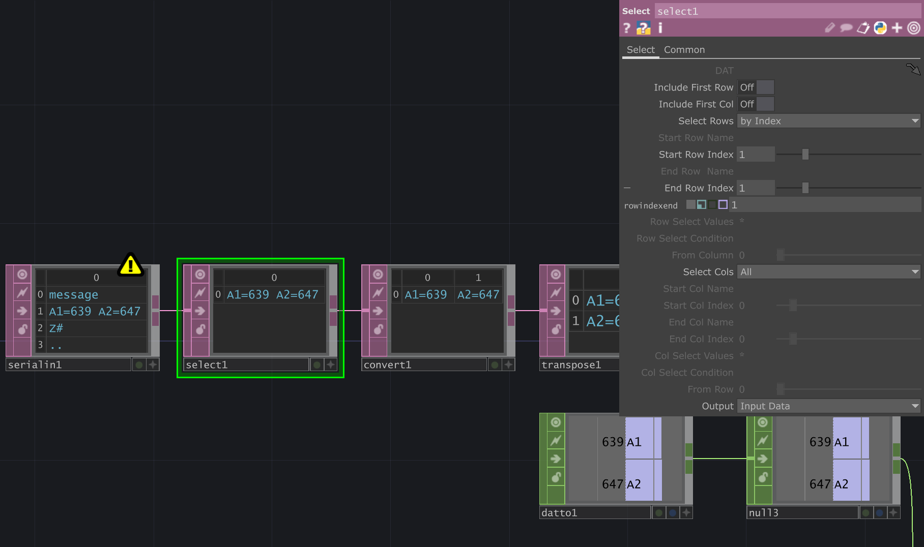
The next box (select1) selects just one row (i.e. one line of received data, one message).
Note the 'Start Row' and 'End Row' index are both set to 1, i.e. it selects just the second row.
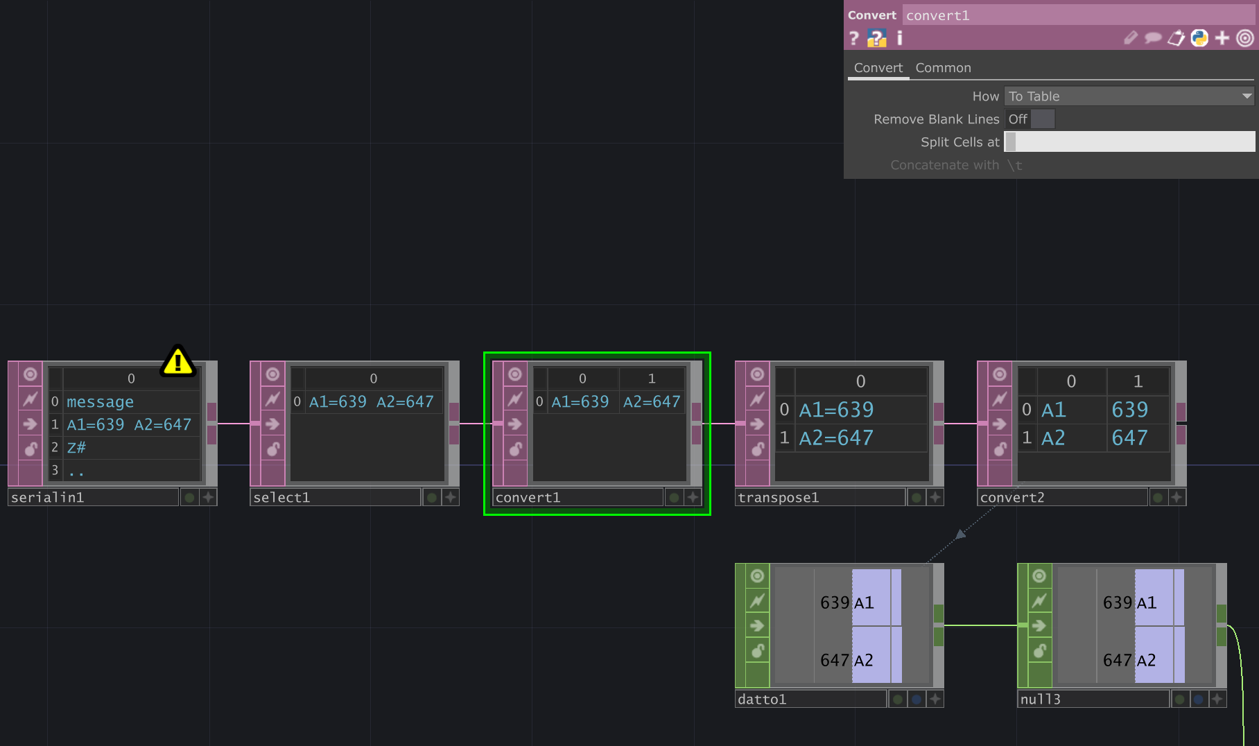
The third box (convert1) splits the line up into multiple cells. Have a close look at the "Split cells at" box - it contains a space character (' '), which will make it split the message at each 'space'.
The result is two cells: each containing an Arduino pin name and the corresponding sensor value. (e.g. "A1=639")
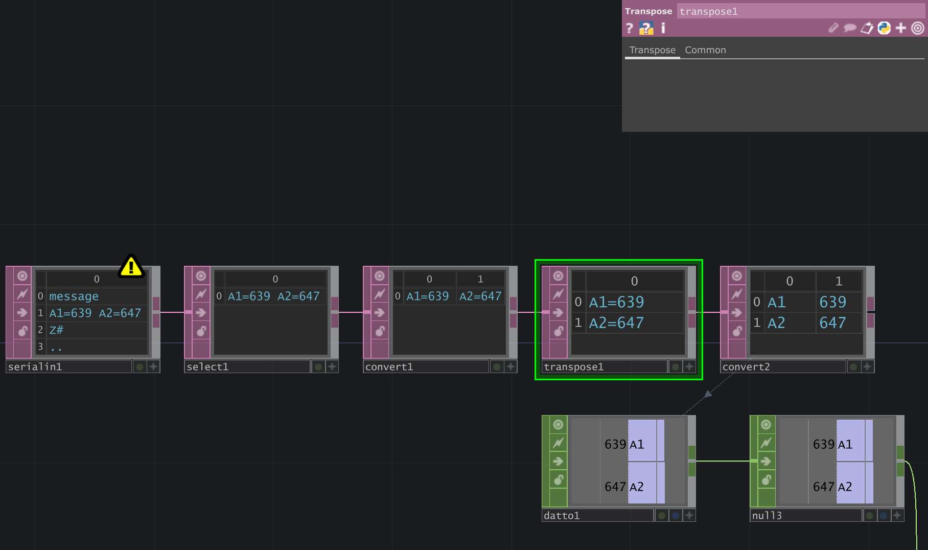
The next box takes those two cells and transposes them - i.e. it turns table rows into colums.
Now you have two lines / rows, instead of the two cells side-by-side
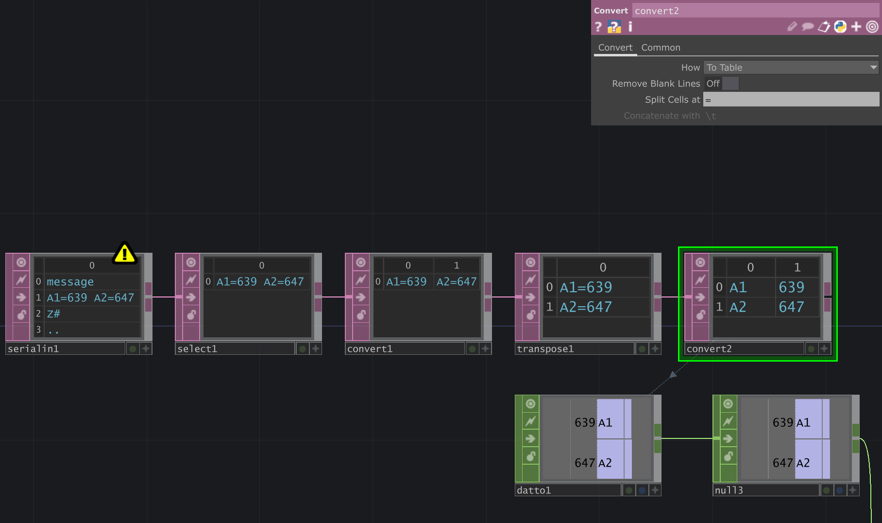
The last convert box (' ') takes these two lines and splits them again, this time cutting the message up at the '=' character.
We now have a table of sensor pin names, and their corresponding values.
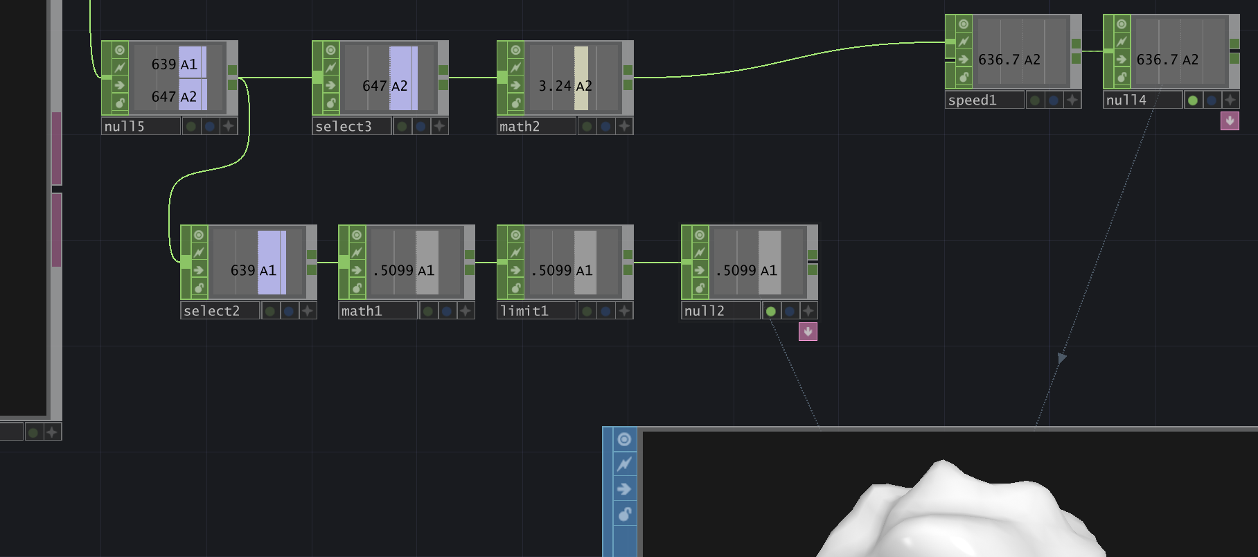
Finally, the 'Dat to' box (datto1) converts the table into single number 'channel' operators (CHOPs) that you can use as input to drive your own audiovisual effects.
The sample uses them to adjust the speed and magnitude of the sphere's wobbliness - but you can go all-out creating your own effects!