Step1 - UltiMaker Cura Set-Up
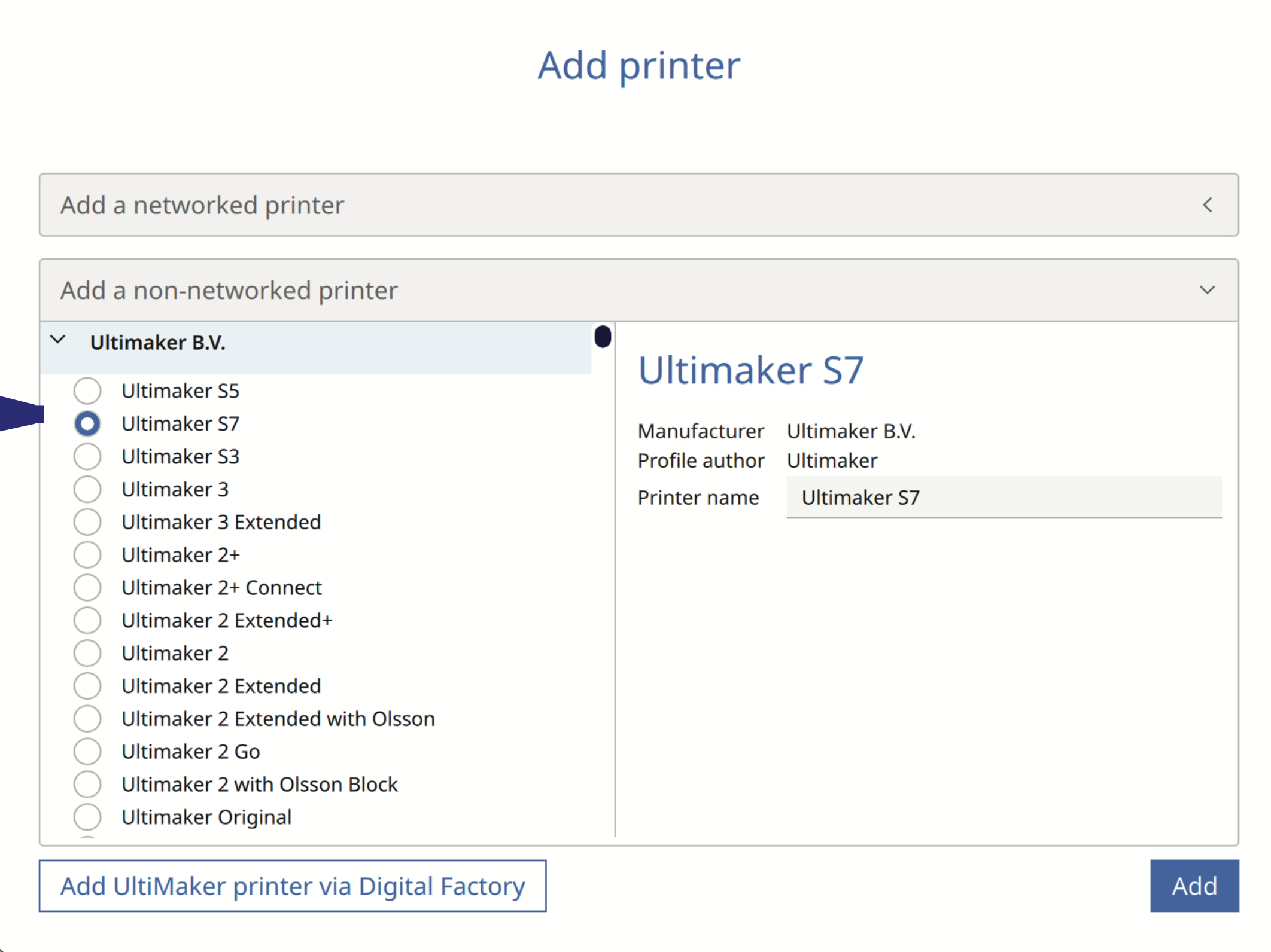
Add an S7 Machine
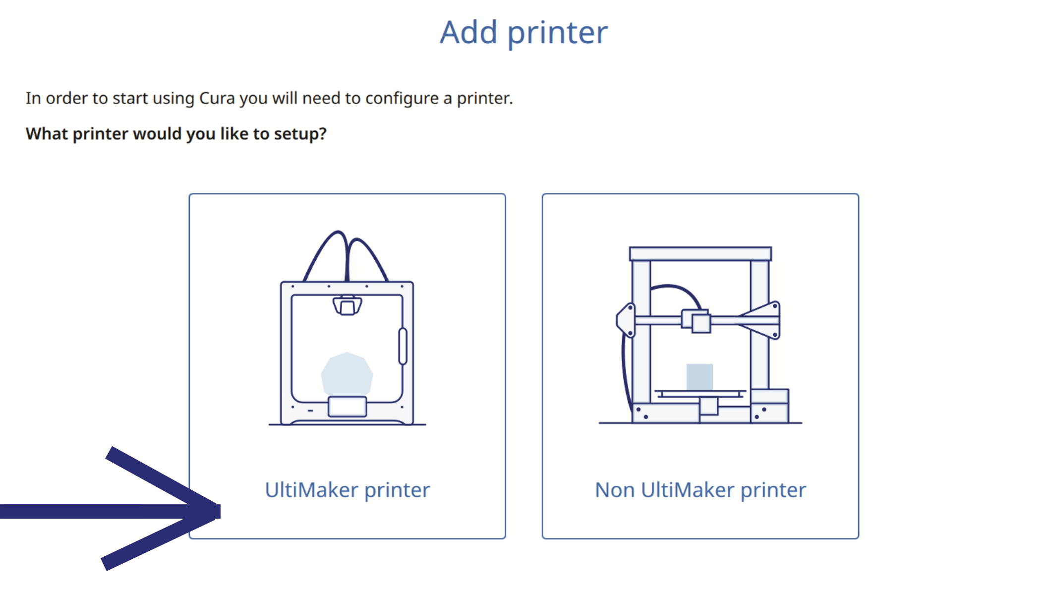
1. Add an UltiMaker printer from the start menu.
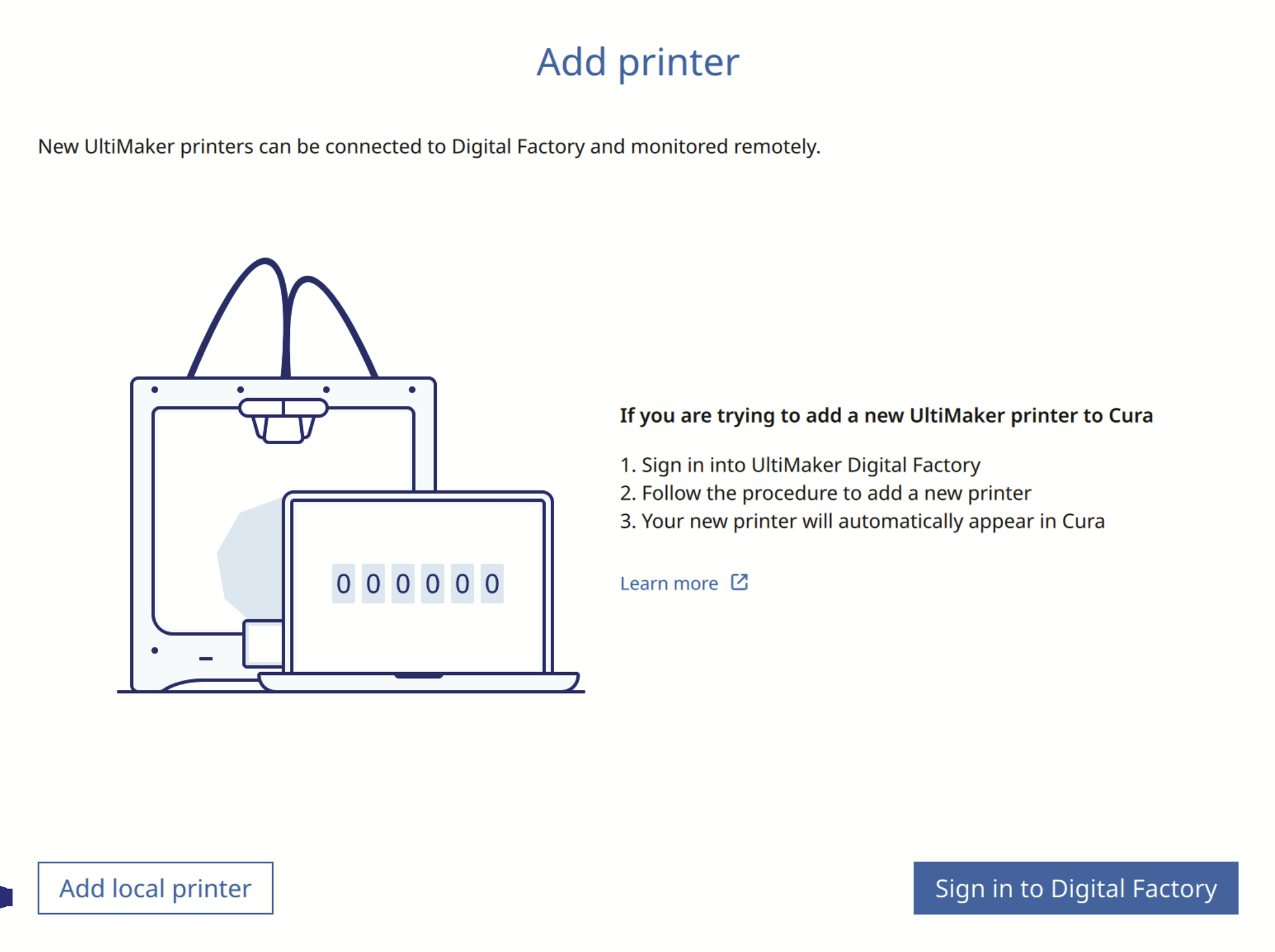
2. Add a local printer from the start menu.
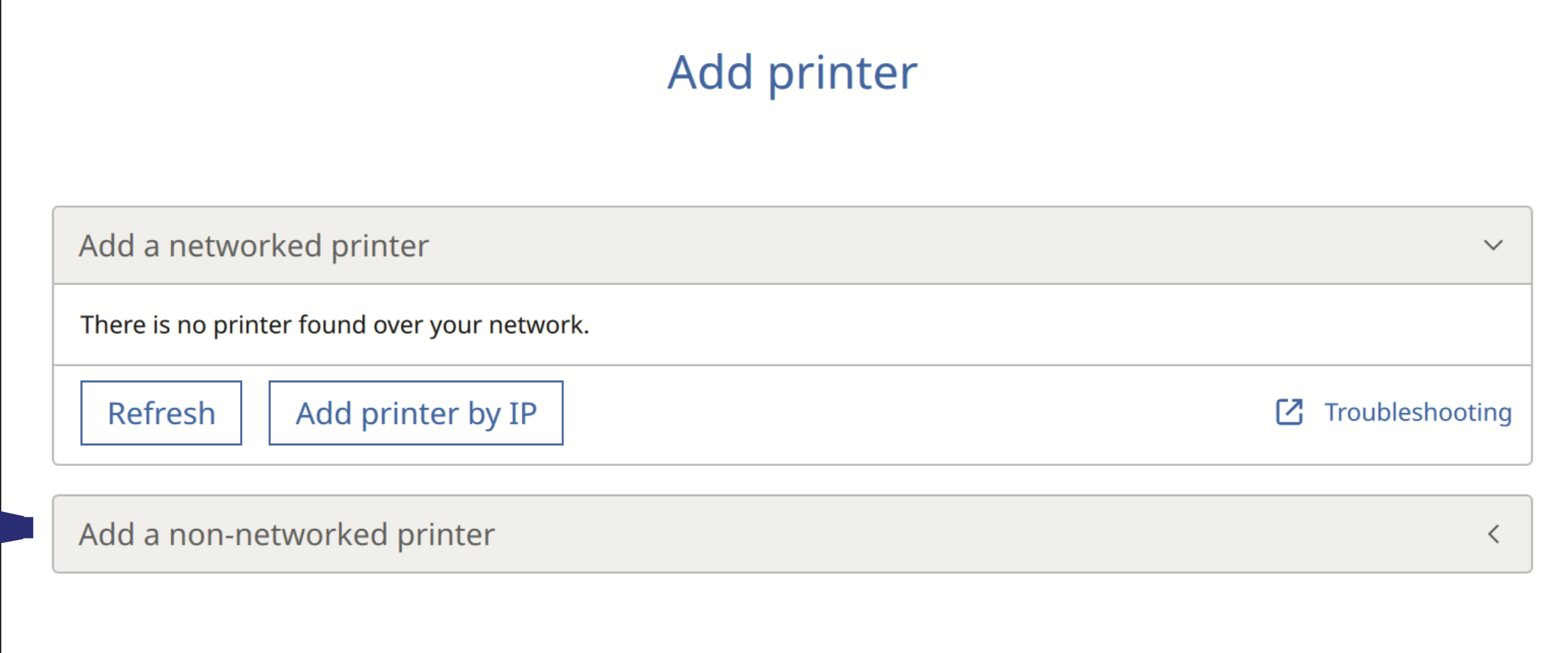
3. Add a non-networked printer from the start menu.
4. Add Ultimaker S7
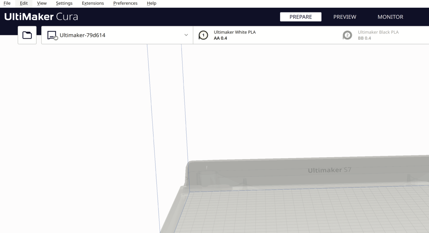
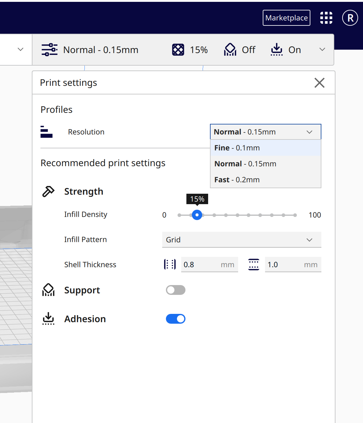
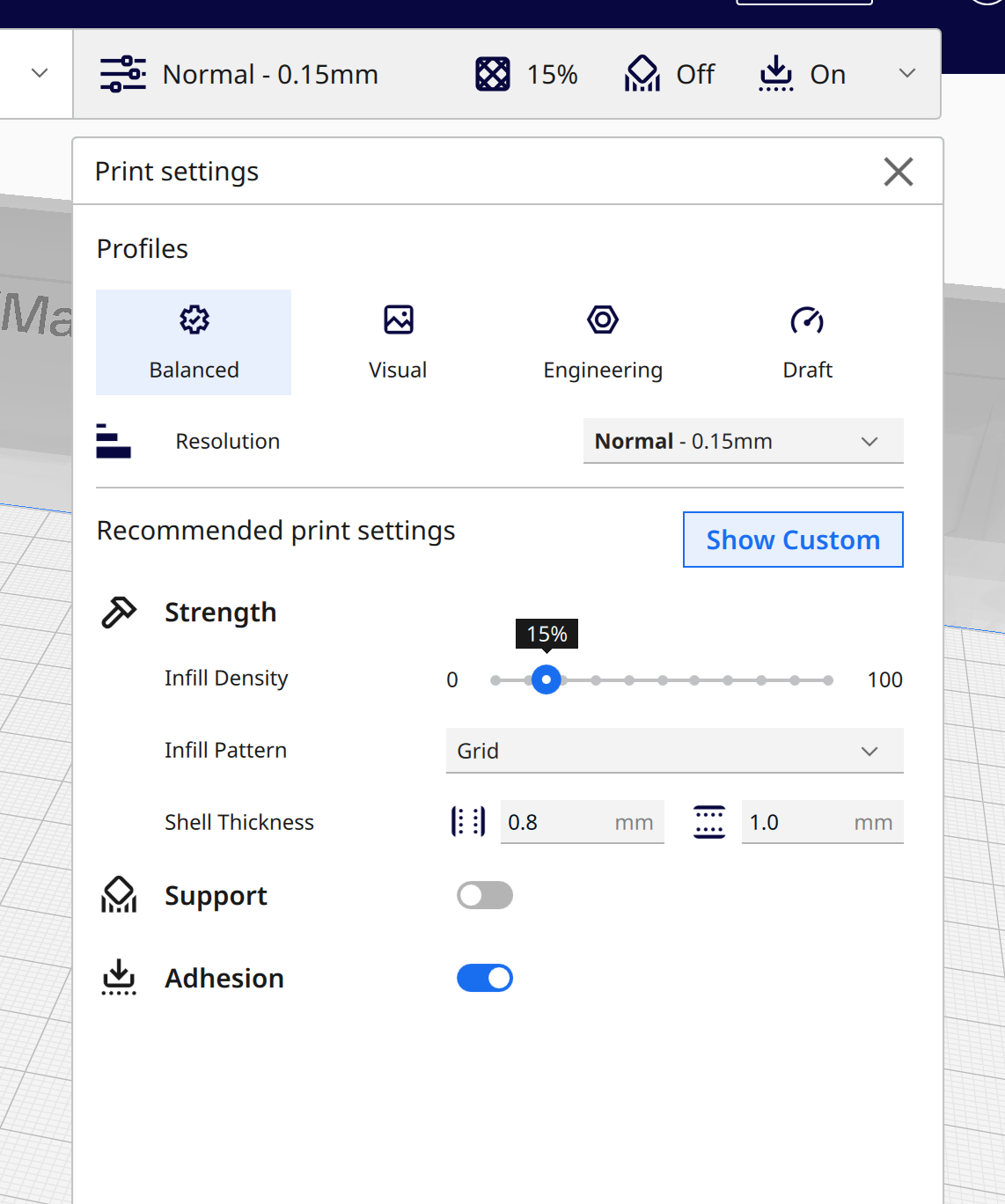
Prepare Window
This is the preparation window, which shows the bed size of the Ultimaker S7 (330 x 240 x 300 mm), select the filament type and color, as well as set up the values such as print resolution, which affects the length of time it takes to print, as well as the material infill density.
-
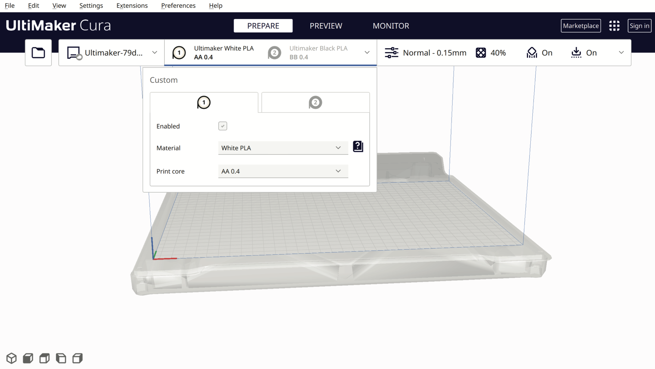
Press the Folder button to import your STL/OBJ/3MF file into Ultimaker Cura, or drag and drop files into Ultimaker Cura.
-
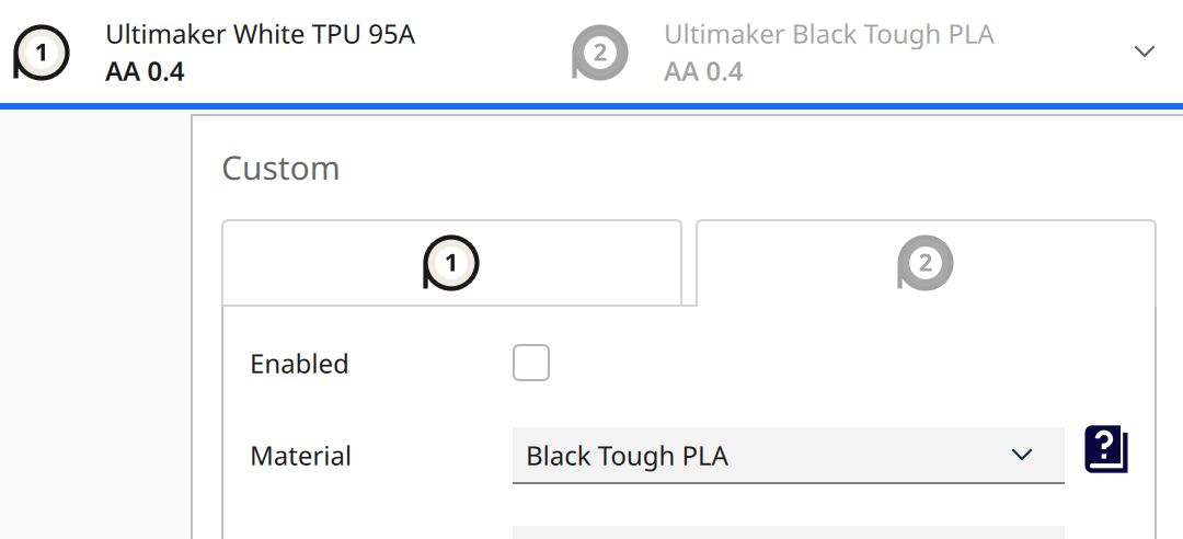
In the drop-down menu, select the type of filament, e.g. PLA, Tough PLA, PVA, TPU, Breakaway and the filament colour. In this example, we are using UltiMaker White PLA from extruder AA 0.4

-
Enable and disable the filament extruder heads by ticking the “Enabled” box. (Please uncheck the second extruder option; we will cover the dual-extrusion option in our advanced 3D printing workshop)


Material Setting
- The build plate temperature should be set to 75°C;
- The material temperature setting depends on different materials, and the support overhang angle should be 45°.
- Go to the Show Custom page to change them.


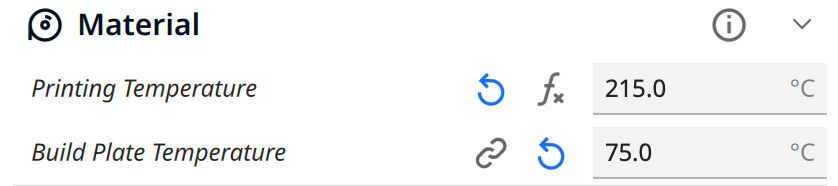
If you are using PLA, please follow the basic settings below; with them correct, your prints won't go too wrong.
Material
Printing Temperature: 215 °C
Build Plate Temperature: 75 °C
(This printing temperature setting is for PLA; different filaments need different settings; default settings won’t work, make sure you set them correctly in UltiMaker Cura. For more info about different materials, please refer to the Filaments page. We'd strongly recommend starting with PLA)
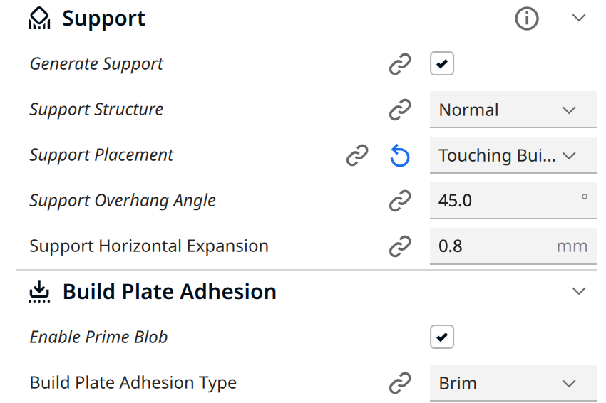
Support (if the object needs support)
Enable Generate Support
Set Support Overhang Angle to 45°
Build Plate Adhesion
Enable Prime Blob
Set Build Plate Adhesion Type to Brim
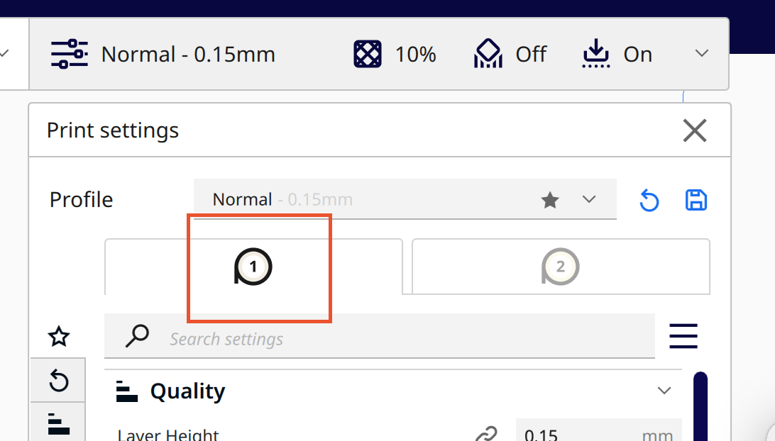
Make sure you've chosen the first material bar
--
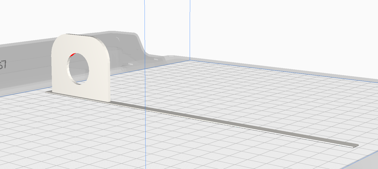
Import and Check Your Model
Import your model, then adjust the settings accordingly when needed. If there is anything shown Here is a breakdown of the model colors in the Solid View (Prepare) mode:
- Material Color (e.g., Light Grey/Yellow): The default color of the model, representing that it is properly positioned and sliced with the currently selected material.
- Red (on bottom surfaces): Indicates areas that are steep overhangs (usually (>50) degrees) that may need support to print successfully.Red (on top surfaces): Usually means the mesh normals are reversed (flipped) in your 3D modeling software.
- Light Blue (on bottom): Indicates the area of the model that is in contact with the build plate.Striped Grey/Darker Overlay: Indicates that the model is outside the printable area or partially below the build plate. Indicates the areas of the model that are in contact with the build plate. Always check that the bottom of the model is correctly touching the build plate—especially when printing multiple models at once. Although they may appear to be on the same plane, some models might have been exported with their Z-axis not set to 0. Ensure the light blue areas are properly grounded on the build plate, or use supports / build plate adhesion if necessary.
- Yellow/Orange Settings: If numbers in the settings panel turn yellow or orange, it signifies a warning that the setting might cause issues, though it is not a fatal error