Electronics Fabrication Tips, Tools and Resources
Here at the CCI, only a few courses require students to go beyond breadboard prototyping of circuits, and in lots of cases this might be all you need to develop your prototypes. However, for students that are interested in developing their hardware work, either to make permanent installations, to make work for others, to make wearables, or just to have more reliable circuits, there are a lot of useful tips and tricks that can make your life a lot easier!
These notes were written by Agnes for a Technical Skills Workshop. This guide is written in order of the stage of prototyping -- normally to make a new circuit I'd go through all of these!
0. General fabrication tips and info
- make lots of tests before soldering everything together! do things a small bit at a time
- always check for shorts before you plug stuff in
- it's a good idea to breadboard your ideas and get them working before doing anything else
Components and materials
You can fabricate a lot of really diverse and complex circuits just using the free components we stock in the Physical Computing Lab. There's a big big guide to these here.
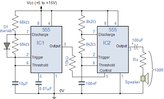
Working from Schematics
If you're trying to make circuits that you've found online or in a textbook, they might come in a variety of formats. In addition to pictorial representation (like Fritzing diagrams, or pictures of breadboards/stripboards), it will be possible in most cases to find a 'circuit diagram' or schematic. These take a bit of practice to learn to read, but it's well worth doing if you plan to do any more complex hardware work. There's a good guide to doing this here.
Often, working with a circuit diagram involves being systematic -- it's a good idea to work from nodal points where multiple things connect together, or work in order of pins on an Integrated Circuit. For more on this, there's a fantastic guide called The Art of Debugging Circuits, which goes through a bunch of different strategies for electronics debugging. A sample quote here:
A circuit appears magical when their is a conflict between your logic and physics. Remember: physics is never wrong (with respect to conventional circuits). Circuits always behave logically. Your circuit is doing exactly what it is supposed to do the way that you built it. Your logic is wrong. This can either be because you do not understand what you built or you did not build what you understand.
1. Better Breadboarding
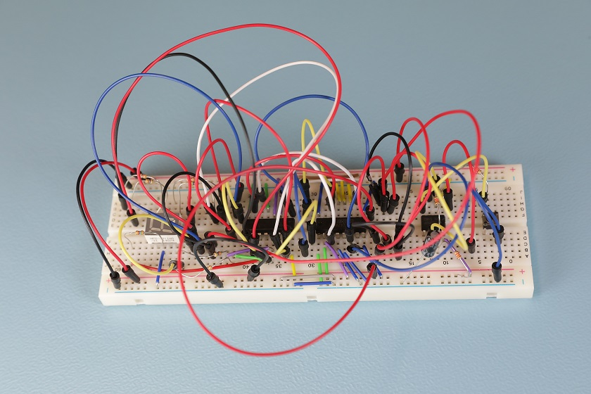
Often, the first step when prototyping is to make and test the circuit on a breadboard. Even when breadboarding, though, there are some ways to make your life a lot easier. One of the first things I'd recommend doing is to use solid-core wire rather than header wire on the breadboard -- it makes it a lot easier to see what's going on.
bad: spaghetti
good: some kind of other much more legible pasta shape
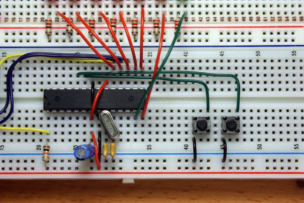
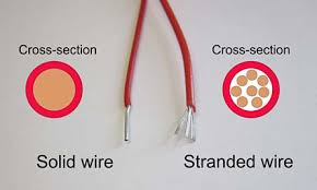
The second of these, instead of using header wire, uses what is called "solid core wire". This is wire with a single piece of metal inside, and can be bent into shape. We stock both stranded and solid core wire in the department -- stranded wire is for making flexible connections between boards. To know what you have, either try bending some, or strip a little from the end.
To correctly arrange solid core wire, the easiest way is often to strip one end, and put it into one of the holes it needs to go into. Use your thumb to mould thw wire toward where it needs to go, then cut with 5mm to spare, strip the other end, and insert into the board.
Breadboarding Rules:
- always use the power rails -- use red for the positive voltage, black for ground (see below)
- always connect all the grounds in your circuit together
- use solid core wire rather than header wire to connect components together -- you can mould this onto the board, and it makes it much easier to see what's going on
- colour code your wires to stand in for different kinds of signals, so you can easily 'read' what's going on (e.g. use green for PWM, orange for analog inputs). There's not the same conventions for this as the power rails -- just choose what feels right
- always plug the power in last, and unplug it again before making any edits
- give yourself enough space! breadboards have little notches to attach together. A rule of thumb with circuits is always to start big, then think about making things smaller
cardinal rule:

Breadboarding Guides and Resources
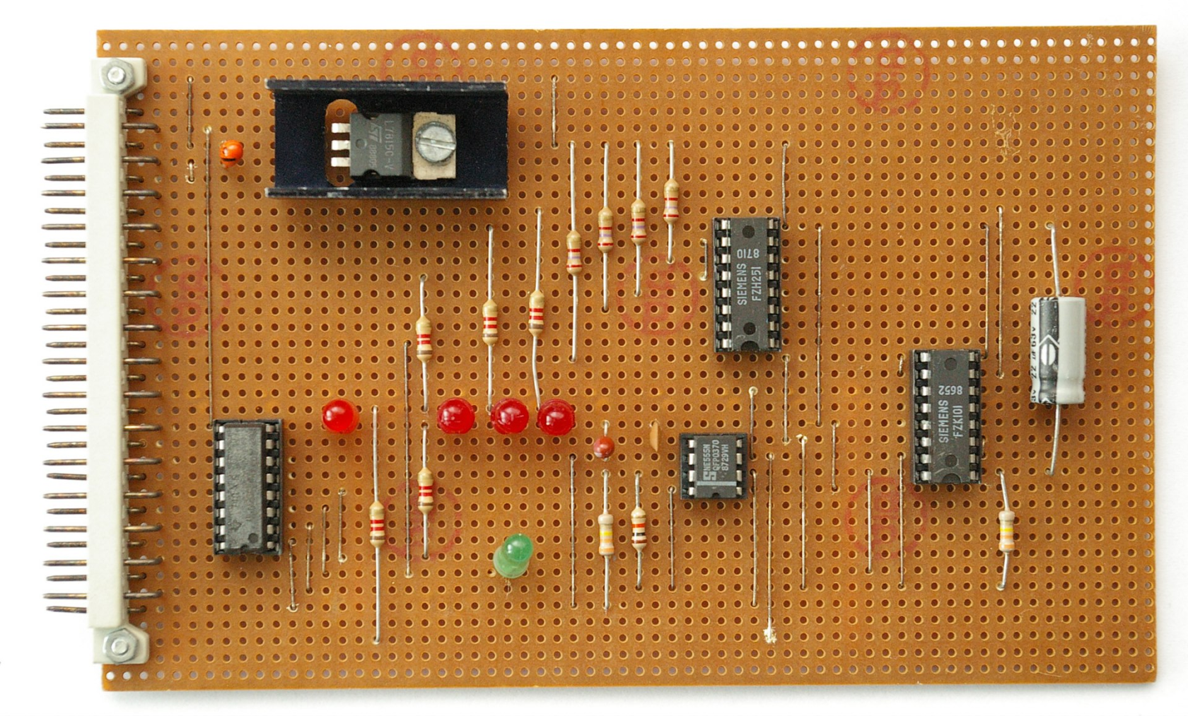
2. Soldering and Stripboard
For one-off prototypes, with smaller and not so complex boards (+ where it doesn't matter so much how large the board is), the stripboard/protoboard stage can often be a good place to stop. It holds all the components in place, and, so long as you pick the right connectors, it shouldn't break.
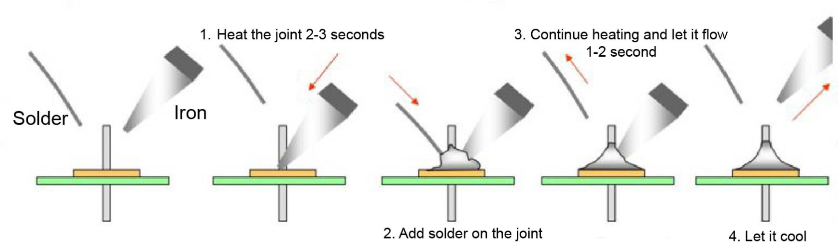
soldering
We have a whole separate guide on how to solder properly! A summary of good soldering technique is given here.
please never
do this:
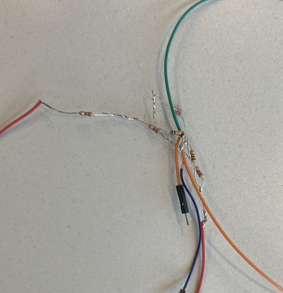
😬 looking at you, Modular students!
Stripboard Guides and Resources
- The Lost Art of Stripboard Prototyping -- this is a fantastic guide, really worth giving it a read, even if you've made stripboards before
- How to Solder: A Complete Beginner's Guide -- good guide to soldering technique
General stripboarding tips:
- lay all your components out before you start soldering. Most components you can bend the legs of to hold them in place, and it's helpful to be able to rearrange things as you decide on your layout
- start by soldering low-rise things first -- if you solder in large components your board won't be able to lie flat when it's upside-down
- you can use a craft knife to cut traces e.g. in between the legs of an Integrated Circuit
- always do a sanity check when you are starting to make sure the copper traces are the correct way round
Connectors
Amazing Resource -> The Electrical Connector Book
One of the major decisions that you will make in any electronics project is what connectors to use, e.g. to connect different boards together, to make a connection to a power supply, connect components such as motors.
The first major major rule is -- never just solder a connecting wire directly into a stripboard. It will break!! Always plan to use a connector to interface to the board.
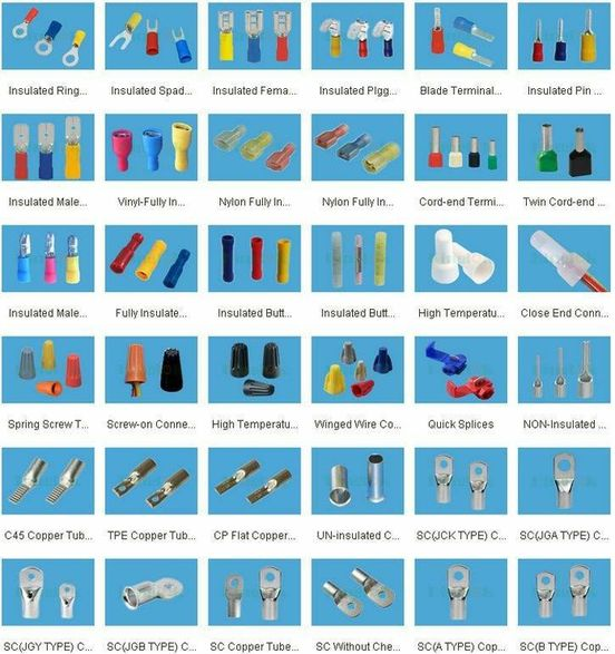
With things like connectors, it can be really useful to know a few common types, and to be able to identify ones you might run into! There are loads of different ones suitable for different scenarios, I'm linking the main ones here.
General considerations
- what spacing ('pitch') is the thing you are connecting to? Arduino, Raspberry Pi, breadboards and most prototyping boards have a pitch of 2.54mm. This isn't always true for other boards and components, however -- for example the Adafruit feather boards use a 2mm JST connector for the power supply, and Grove components are all 2mm Molex
- what gauge of wire is being connected? thicker wires might not fit in smaller connectors, and vice versa. This is particularly important for crimped connectors such as JST
- do I need strain relief? for connections that might move a lot, or are subject to lots of force, it might be worth considering how to securely mount these on your board, past just soldering, or how to protect the joins
- do I need a special tool to use this connector? some connectors, like JST, also require a specific crimping tool to make the connection. These can sometimes be really expensive, and/or hard to use
DuPont
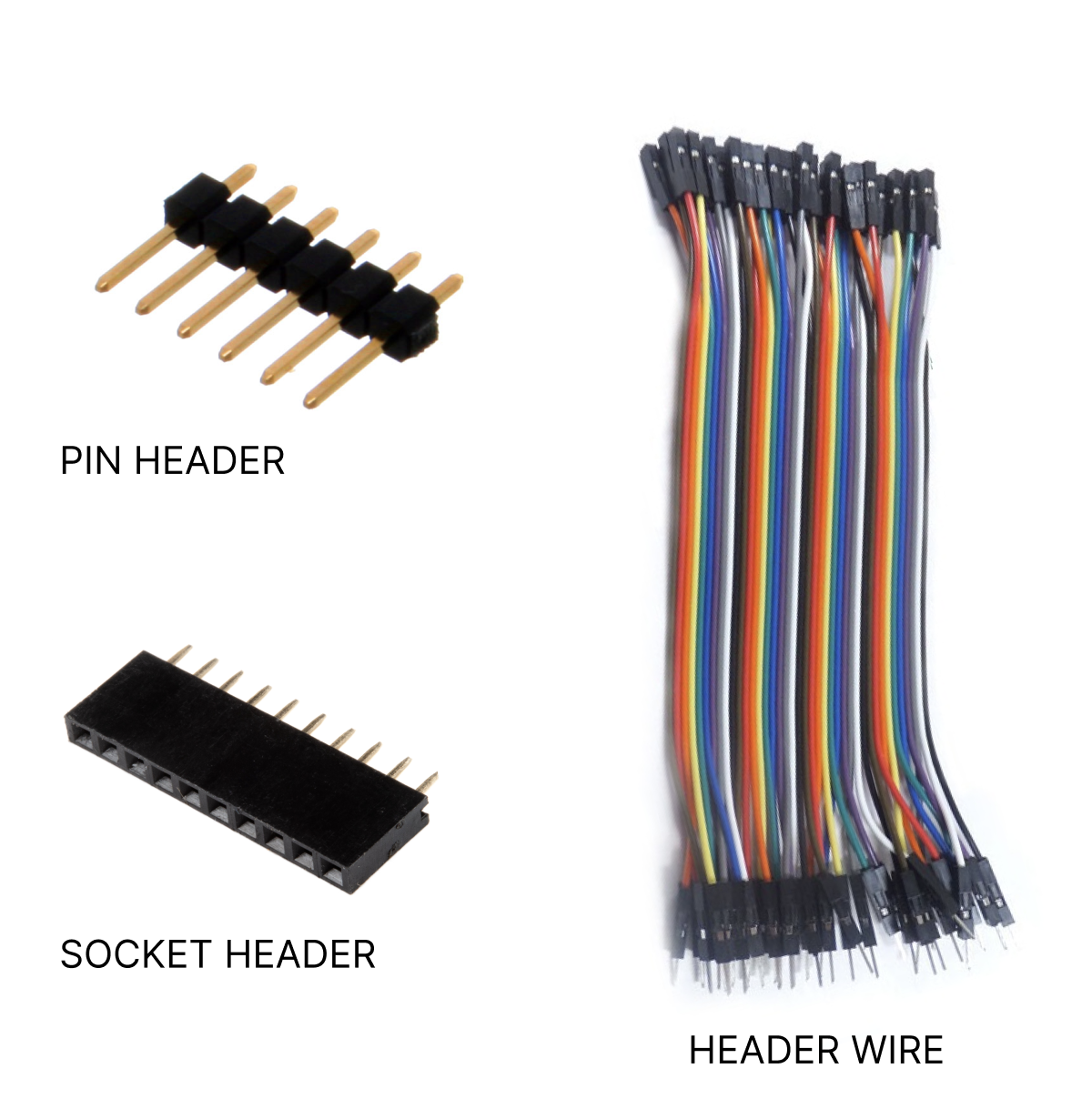
You will probably be familiar with DuPont connectors from using header wire to connect components to an Arduino. They are very commonly used in prototyping boards, which often come presoldered with Dupont-compatible headers or sockets. Their main drawback is not being very well fixed-in place: if you've ever had a breadboard come apart during transit, Dupont headers are likely to blame.
Good for:
- temporary connections
- low current
Not so good for:
- anything permanent
- power supplies
JST
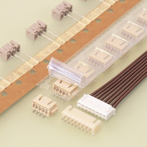
JST connectors are my go-to for developing small projects. They can be fiddly to create (they often require manual crimping), but are a great balance of manual adjustability and reliability once you've got the hang of working with them.
JST can be a tough standard to get your head around, and I always recommend taking a look at this guide when starting to work with them. The JST-XH standard corresponds to the 2.54mm spacing standard used on most boards, but do always double check that that's the pitch you want to use.
Good for:
- one off prototyping
Not so good for:
- if you're in a hurry and just want to test something (use Dupont/solid core wire and a breadboard)
- large arrays of connections (use IDC and ribbon cable for anything > 5)
IDC
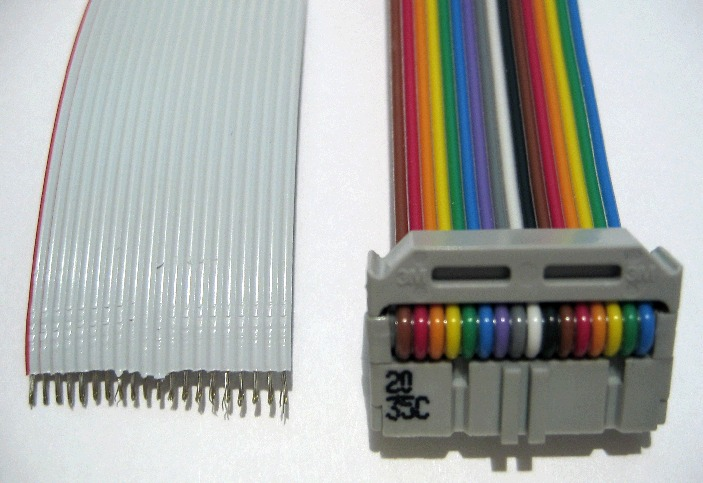
IDC stands for "insulation-displacement contact" -- they are used with ribbon cable, and have tiny blades that slice into the cable to create electrical contacts.These are good if you have to connect multiple cables together, and are often used to communicate between boards.
They normally use 2 rows of pins, so if you're attaching them to a stripboard be sure to score between the rows to prevent shorts!
These can be very convenient, it's a quick way of making a bunch of connections. Unlike JST, however, it's not possible to disconnect and reroute individual wires.
Good for:
- inter-board communication
- quickly making a bunch of connections
Not so good for:
- smaller numbers of connections
- I always find that I need to think quite hard about which cable connects to which pin. But perhaps you enjoy thinking about such things
Screw Terminal
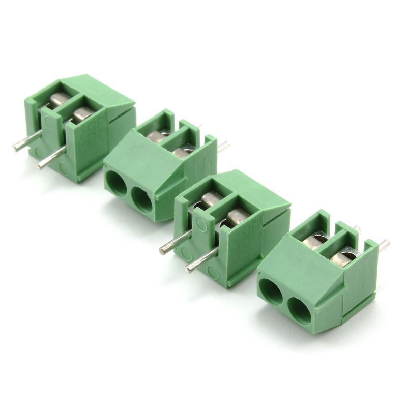
Good for:
- power supplies
- components like motors that you might need to often connect and disconnect
- anything with a strand-core cable that's slightly too thick for JST
Not so good for
- small spaces
- overkill for low-power components
Crimp terminal connections
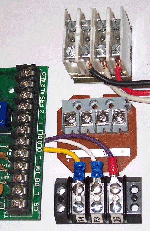
In the above image, you can see that the wires in the screw terminal at the bottom are much more safely connected than those at the top.
While connecting smaller-gauge wires that don't carry high current, it can be fine to just connect the wire into a terminal as-is. However, for thicker cable, you will need to crimp the ends to ensure a secure connection into the terminal block. We have loads of these in different sizes at the CCI -- they can be quite forgiving, however it's worth taking some time to make sure you're using the right ballpark wire gauge. Here's a lovely chart of all the variants: I default to using the ring connectors.
Proprietary connectors
Some connector standards are associated with particular kinds of cable. Common ones to encounter in board fabrication are for programming boards. To allow your board to be programmed by one of these (this is a particular consideration for PCB design) you might want to include the specific footprint of the connector you need (often this is a kind of header).
Common proprietary connector standards include:
- ISP -- 'in system programmer' -> these are a funky little 6-pin arrangement that you get on more specialised boards. Used as an alternative to programming a board over USB.
- JTAG -- often used to debug chips on boards
- FTDI -- these are actually pretty convenient as they just use regular dupont headers
A note on language -- lots and lots of electronics manufacturers will still use the gendered terms 'male' and 'female' to describe the orientation of connectors. This is language that's essentialist and reductive, and lots of places (including the CCI!) use 'plug' and 'socket' instead respectively -- but if you are searching for connector types online it can be useful to have these as search terms as they're still used quite widely!
For a good time, you might enjoy the twitter account cursed connectors.
Wire gauge and Power Considerations
With circuits that need to handle either movement or higher loads, what wire you use can become a major consideration. Adafruit have a great guide to understanding wire gauge and picking the correct wire for your project.
In general -- the generic thinner wires we supply at the CCI (I believe these are 22 gauge) are fine for most microcontroller projects where the current is <1 Amp. If you are using components that consume more current (like larger motors, speakers, amplifiers etc), and especially anything using mains, you will want to do some power calculations to figure out what wire to use. Do come and speak to a technician if this is the case, we can help. The thicker the wire, the more current it can handle.
High-power circuits shouldn't be prototyped using breadboards. Stripboard can handle higher currents, but it's a good idea to thicken the traces that will be taking these currents with an extra layer of solder. This will reduce resistance and prevent the circuit from heating up.
Omni have a useful wire size calculator that allows you to figure out what gauge of wire your project might need.
IC sockets
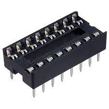
Never solder an integrated circuit (IC) directly into a proto board!!! You'll end up with loads of issues later on. Instead, solder an IC socket in -- this way if you have issues with your IC (like, you accidentally blow it up), it's really straightforward to change it out without having to desolder a load of pins.
It's a good idea to put all your ICs in the same orientation -- this makes it a lot harder to put one in the wrong way round (incidentally a great way to blow things up).
3. PCB Fabrication and Milling
The next step up from prototyping on stripboard is to fabricate your own boards. There's a few different ways to do this, and typically this might be a choice you would make if:
- you want to make something in volume (depends on complexity, but this can save you a lot of time even with low volumes)
- you want to make something much smaller (e.g. for wearables)
- you want something to look nicer than proto board
There is a huge amount that can be written about PCB design techniques -- I won't be writing about it all here -- but do reach out if you're interested in more information.
PCB design
Software:
- Eagle -- this has historically been the standard for PCB prototyping, it's been integrated into Autodesk's Fusion360 software. It's possible to get a license as a UAL student if you want to use this, but increasingly KiCad is just as good, free and has most of the same features.
- KiCad -- free and open-source PCB prototyping software. This is getting better all the time and if you're getting started I'd recommend learning this over Eagle
- KiCad Tutorial
PCB Fabrication Services
We recommend a number of different PCB Fabrication services here on the wiki (scroll down to 'PCB production').
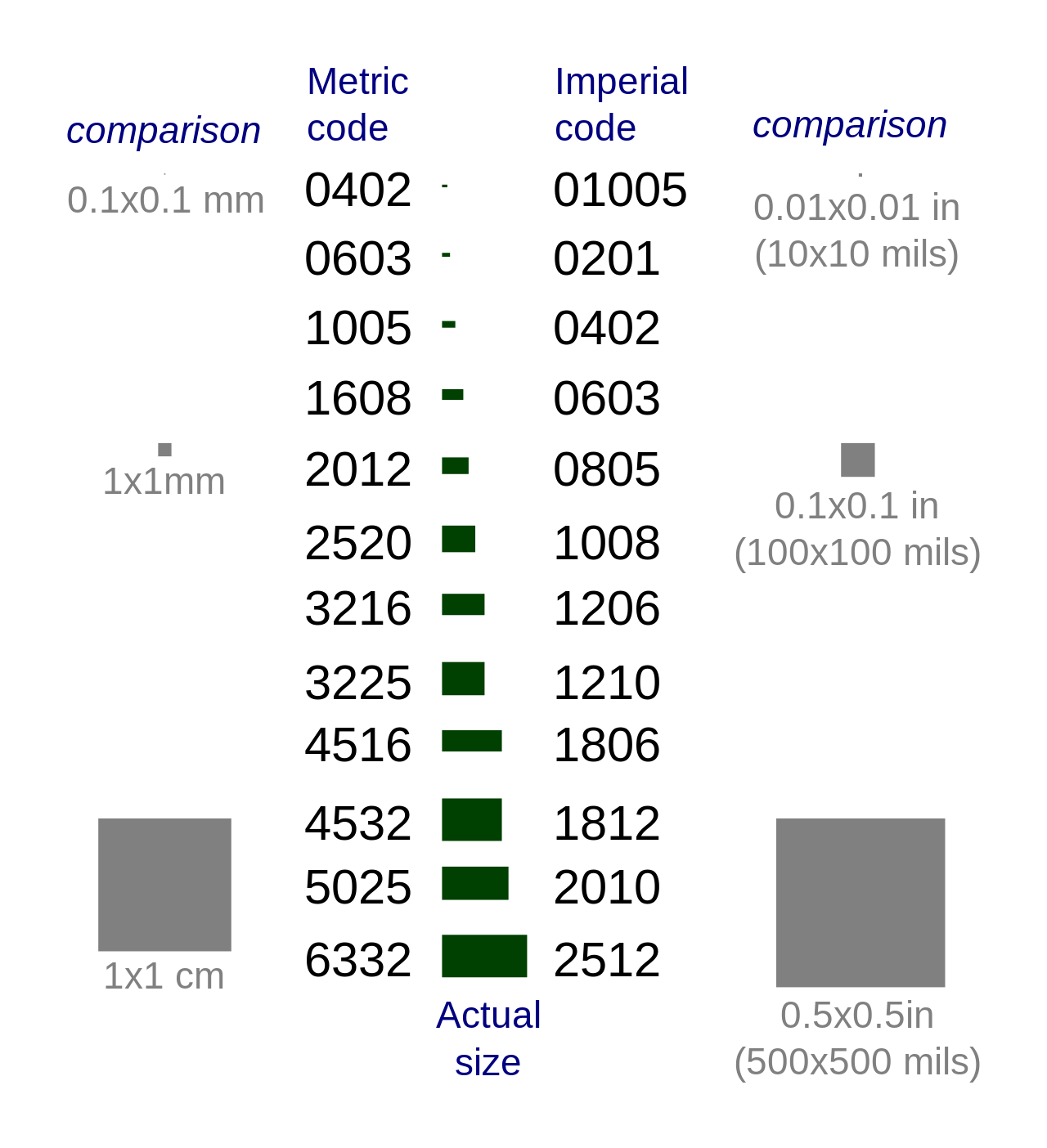
Surface Mount
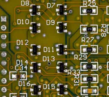
The components we use in the CCI tend to be 'through-hole' components, with legs that pass through the board. These are different from what you might see on manufactured boards, which typically use much smaller components that sit on top of the board material.
These are often a great way to reduce the footprint of your circuit -- so if you're designing a PCB to make things smaller, using Surface Mount Devices (SMD) might be a good way forward. It's possible to fairly easily solder 1206-series SMD components we have with the equipment at the CCI -- much smaller and you might want to pay for the board to come pre-soldered, or else look into using a reflow station.
Other Considerations
Mounting and finishing
Mounting either PCBs or stripboards properly can be very important for ensuring the longevity of your circuit. Often, drilling holes and using spacers / standoffs or just regular bolts can be enough to hold in place. Make sure that your mount doesn't short your traces!
Often it's worth including mounting structures if you're making casing for your circuit, using 3D printers or laser cutters.
Prototyping for Wearables
Wearable electronics comes with a bunch of considerations about size and power management. We stock sewable battery holders for coin cells and 9V batteries, but do not currently stock Lithium Ion batteries, as these aren't allowed on UAL campuses due to fire risk.
Lots of wearable projects involve wireless components (so whoever is wearing it doesn't have to have a USB cable attached to them), so you might also want to look into networking protocols, using either Wifi, Radio or Bluetooth.
There are many options for integrating circuits into textiles, ranging from making conductive textiles from scratch (e.g. conductive knit) to using silicon-coated wire to stitch flexible threads into garments. For project ideas involving textiles, we have a wiki page for e-textiles and the website How To Get What You Want (by the collective Kobakant) is an amazing resource for different project ideas.
I want to make my circuit smaller
This is a pretty classic issue with arduino-based circuits -- you have a circuit that works, maybe built with Arduino, and you want to minaturise it. Here are some options, from biggest to smallest:
- use an Arduino shield -- this is a special prototyping board that allows you build directly on top of the Arduino. This can be nice if you just want to avoid connection spaghetti
- use a smaller Arduino board, like an Arduino Nano or Arduino Micro. These can be integrated directly into a proto board / breadboard
- Replace the Arduino with another ATMEL chip -- these can still be programmed like arduinos, but it's possible to make the board containing them a lot smaller and only contain the parts you need. As these don't have the USB interface, you will need to use a separate board to program them -- luckily, an Arduino can actually be used for this! There's a good guide to doing this here. This same technique (of replacing a whole board with the chip it uses) can be applied to lots of other boards too.
I want my circuit to be wireless
This is another really common thing to want to do. Core options:
- radio -- I love the adafruit packet radios. Main thing to remember is -- for radio, you need 2!
- bluetooth -- NRF52 is a good one to look at here.
- wifi -- technically this is radio but it's it's own protocol. ESP8266.
Remember that even wireless circuits will still need a power supply! A commonly-used format is LiPo batteries. These can be really convenient, but come with health and safety considerations, especially if they are to be worn!
I want my circuit to be soft/flexible
- Silione covered strand-core wire
- Conductive thread
- Conductive ribbon
Adding connections to this can be tricky.
I want my circuit to work outdoors
Depending on how long it needs to last / how much the circuit moves / how waterproof the circuit needs to be, there are a bunch of different methods. This instructable gives a pretty solid overview. Please be careful when using different resins to coat your circuit as some can be toxic! If in doubt (and definitely before bringing into the workshop), speak to a cci technician.
My circuit contains rotating parts
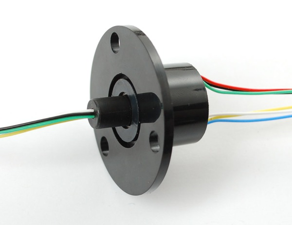
You want to use a Slip Ring. We have some in the CCI -- Adafruit have a video tutorial for how to use them here. A word of warning: this can be a real pain to do, and unless you feel quite confident with fabrication generally we'd advise you try and figure out a simpler way to make your work!