Step 3 - Model Checking
Ultimaker Cura has a workflow based on three stages; the prepare, preview and monitor stage. Each stage has a unique stage menu to efficiently go through the 3D printing process.
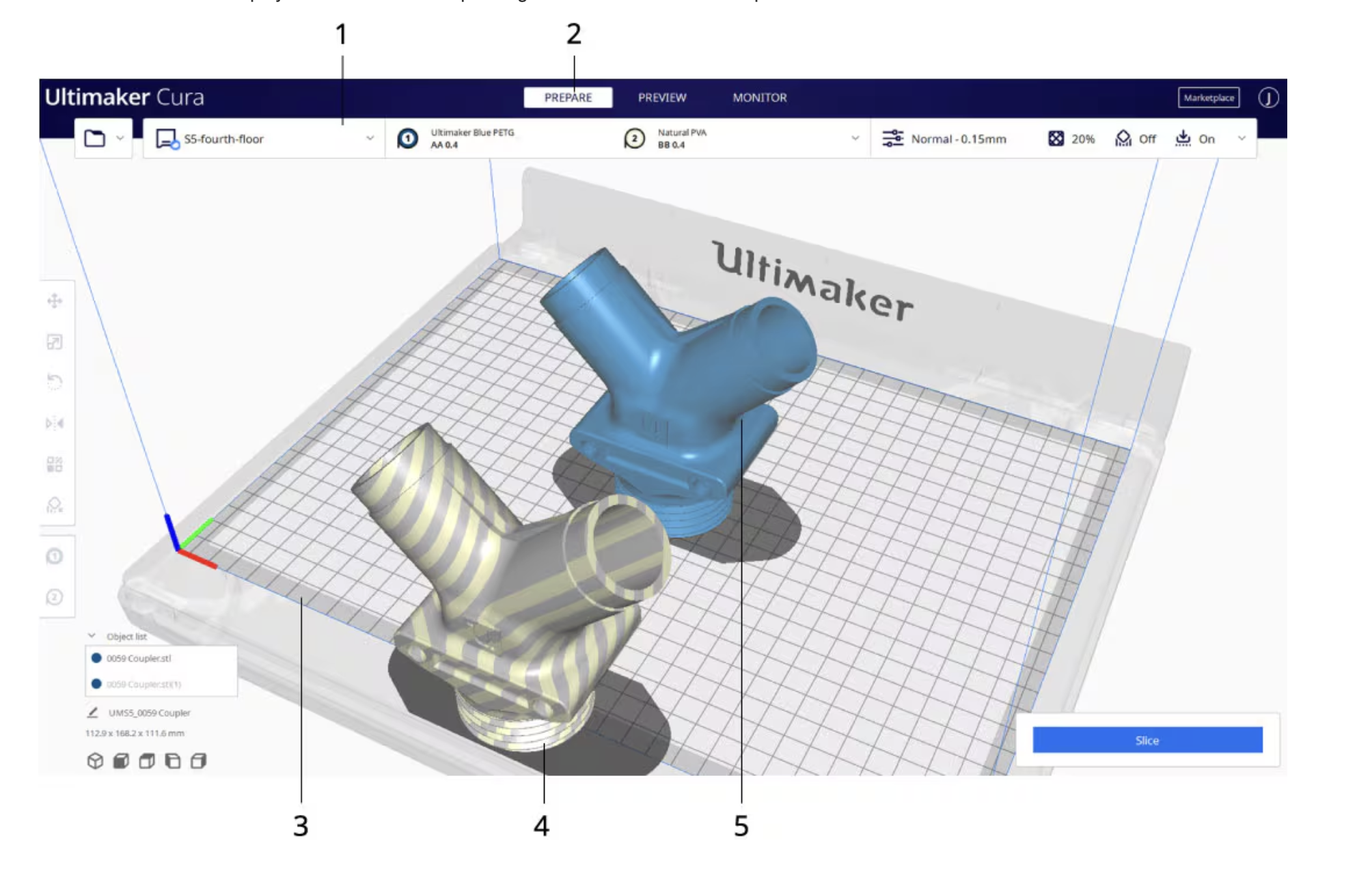
Prepare Page
The prepare stage is the first stage. The goal of this stage is to load and configure your 3D models for printing.
3D models loaded on the build plate are displayed solid, in the color corresponding to the material selected to print with. Models not fully within the printable area have a striped grey overlay. Non-printable areas on the build plate are displayed with a grey border, this space is necessary for build plate adhesion and support structures.
Import and Check Your Model
Import your model, then adjust the settings accordingly when needed. If there is anything shown Here is a breakdown of the model colors in the Solid View (Prepare) mode:
- Material Color (e.g., Light Grey/Yellow): The default color of the model, representing that it is properly positioned and sliced with the currently selected material.
- Red (on bottom surfaces): Indicates areas that are steep overhangs (usually (>50) degrees) that may need support to print successfully.Red (on top surfaces): Usually means the mesh normals are reversed (flipped) in your 3D modeling software.
- Light Blue (on bottom): Indicates the area of the model that is in contact with the build plate.Striped Grey/Darker Overlay: Indicates that the model is outside the printable area or partially below the build plate. Indicates the areas of the model that are in contact with the build plate. Always check that the bottom of the model is correctly touching the build plate—especially when printing multiple models at once. Although they may appear to be on the same plane, some models might have been exported with their Z-axis not set to 0. Ensure the light blue areas are properly grounded on the build plate, or use supports / build plate adhesion if necessary.
- Yellow/Orange Settings: If numbers in the settings panel turn yellow or orange, it signifies a warning that the setting might cause issues, though it is not a fatal error
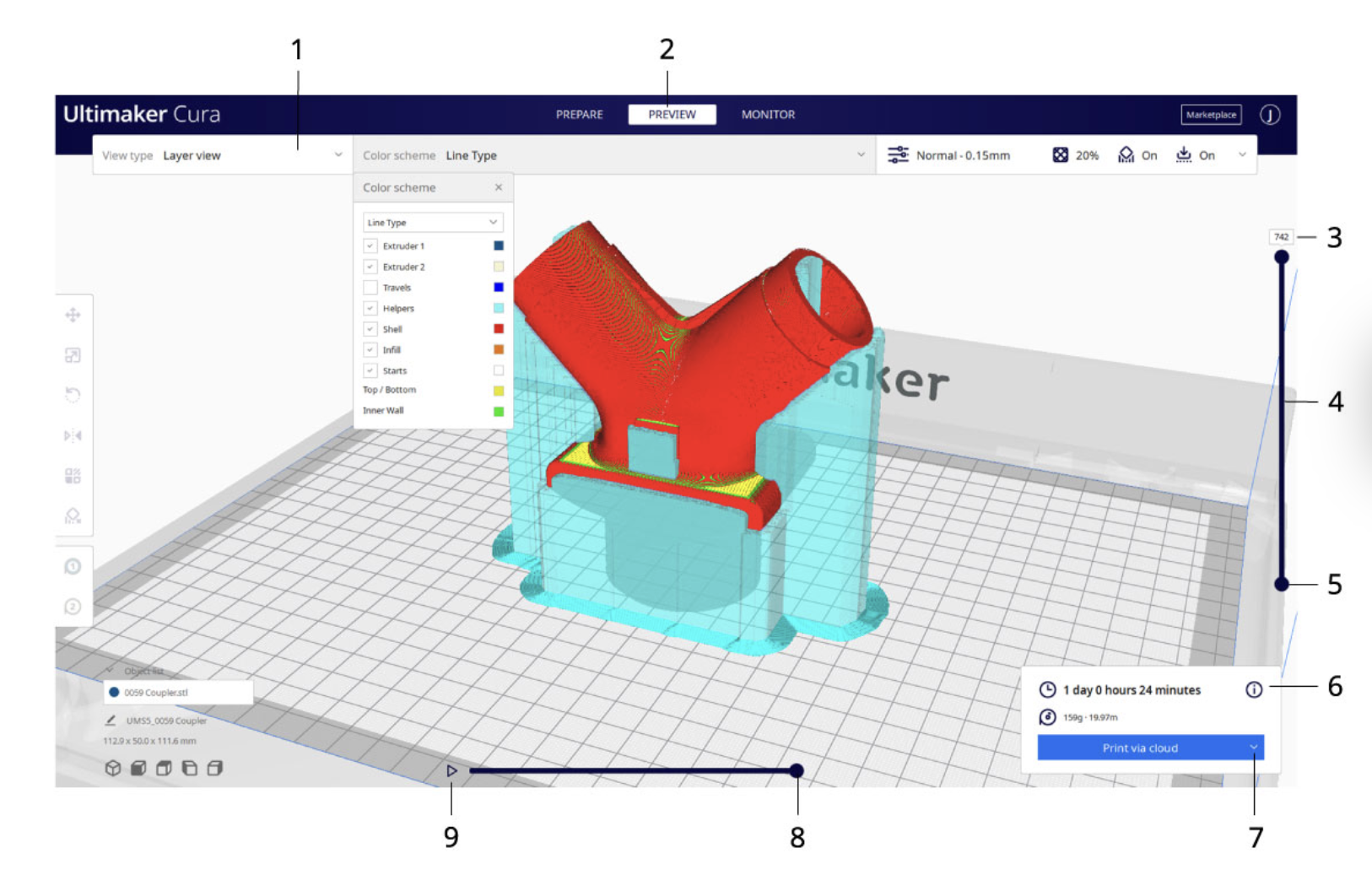
Preview Page
The preview stage is the second stage. The goal of this stage is to preview and evaluate the 3D printing process. This stage can only preview the printed model when the model has been sliced with the action button in the bottom right corner. When going into this stage, the layer view opens automatically.
Layer view
When the layer view opens, your sliced 3D model is visible, represented by every print and travel path Ultimaker Cura generated. These are the actual print paths executed by the printer when the print job gets sent.