Design the clearance and tolerance
Design Clearance and Tolerance
Before exporting your model, make sure it has been designed with 3D printing tolerance in mind.
In this guide, tolerance means the designed clearance between printed parts. In other words, it is the small gap you intentionally leave between parts so they can fit, slide, rotate, or connect properly after printing.
If two parts, for example a peg and a hole, are designed to be exactly the same size, they may become very tight after printing.
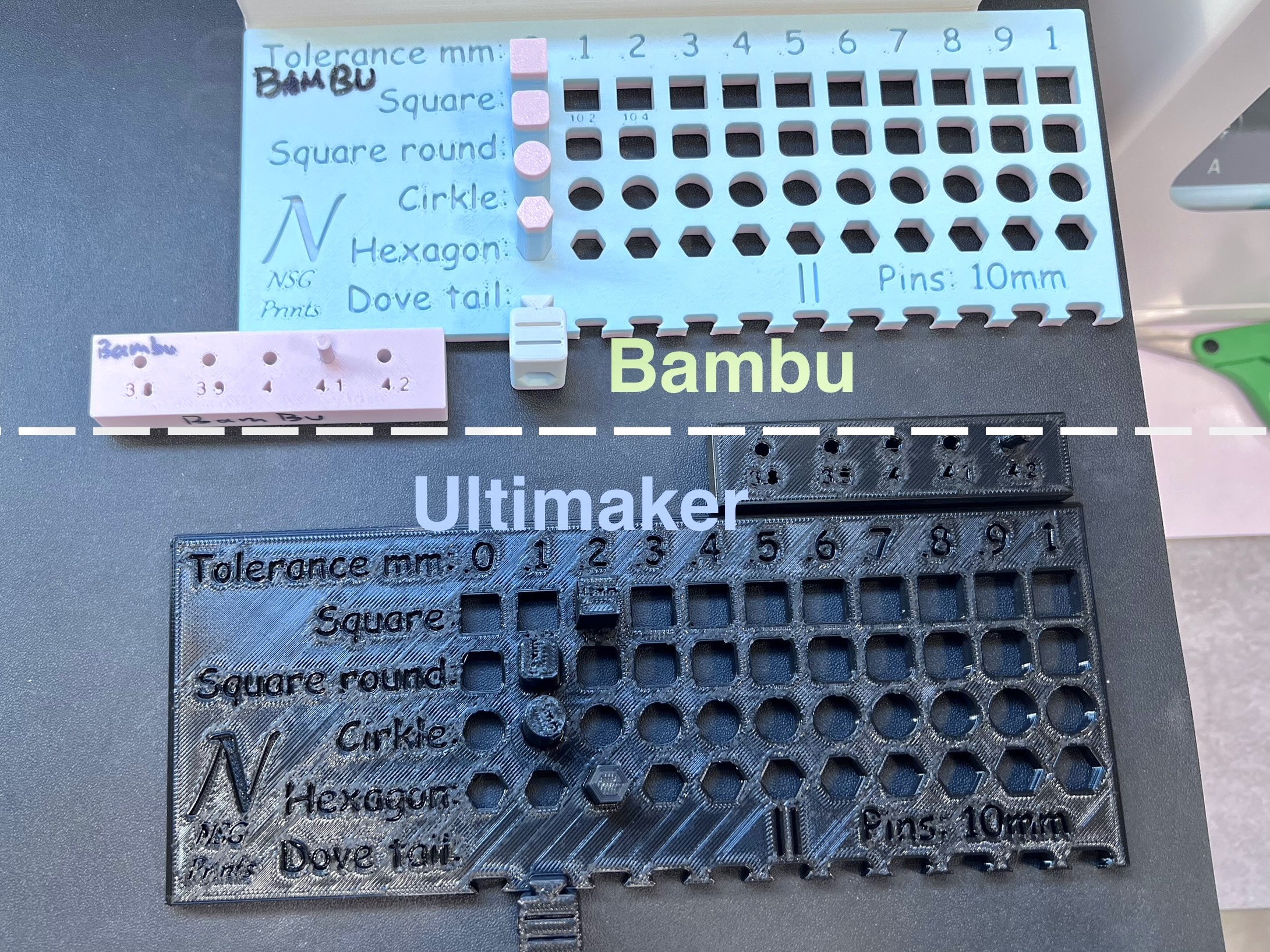
On the Bambu H2D Pro printers, this can sometimes still work for a very tight fit. However, on the Ultimaker S7 printers, the parts are more likely to be too tight and may not fit at all without sanding or adjustment.
How Tolerance Is Measured
When we say 0.1 mm tolerance, this usually means 0.1 mm clearance on each side.
For example, if a cube is 10 mm wide and you choose a 0.1 mm tolerance, the matching hole should be designed as:
10 mm + 0.1 mm + 0.1 mm = 10.2 mm
This means the hole should be 10.2 mm wide, allowing 0.1 mm clearance on each side.
Recommended Tolerances for Bambu H2D Pro
The Bambu H2D Pro printers can usually produce slightly tighter and cleaner fits than the Ultimaker printers, but you should still design with clearance.
For parts that need to fit together, we recommend testing around:
- 0 mm
- 0.1 mm
- 0.15 mm
- 0.2 mm
The correct tolerance depends on how tight or loose you want the fit to be.
Suggested Starting Points for Bambu H2D Pro
| Use Case | Suggested Tolerance |
|---|---|
| Peg and hole for alignment or assembly | 0.1–0.15 mm |
| Peg and hole for removable parts | 0.15–0.2 mm |
| Peg and hole for free movement | 0.2 mm+ |
| Joints, hinges, or sliding parts | 0.15–0.2 mm |
| Press-fit parts | 0–0.05 mm |
| Interlocking parts | Avoid making the fit too tight |
| Screw holes | Depends on the fixing method |
Notes for Bambu H2D Pro
If you are designing a peg and a hole, the hole should usually be slightly larger than the peg. However, it does not always need to be very loose. The tolerance depends on whether the peg is used for alignment, removable assembly, or free movement.
If you are designing joints, hinges, or sliding parts, leave a small clearance so the parts can move after printing.
If you are designing press-fit parts, you can use a tighter tolerance. However, even on the Bambu printers, 0 mm tolerance can still be too tight. The final fit can be affected by:
- Material
- Print orientation
- First-layer squish
- Wall thickness
- The shape of the part
- The contact area between parts
Always test a small sample first before printing the full object, or check the tolerance boards in our lab.
If you are designing interlocking parts, avoid making the fit too tight, especially if the contact area is large.
Screw Holes on Bambu H2D Pro
For screw holes, the tolerance depends on the fixing method.
If the screw is meant to bite directly into the printed plastic, the hole is usually designed slightly smaller than the screw diameter. This is why you may use a negative tolerance such as:
- -0.2 mm
- -0.1 mm
- 0 mm
For example, if the screw diameter is 3 mm and you use -0.1 mm tolerance, the hole diameter would be:
3 mm - 0.1 mm = 2.9 mm
This gives the screw something to grip.
However, if you are using brass threaded inserts, do not simply design the hole based on the screw diameter. The hole size should be based on the outer diameter of the brass insert and the manufacturer’s recommended hole size.
Always test with a small sample first, because different insert types, materials, and printer settings can change how tightly the insert fits.
Recommended Tolerances for Ultimaker S7
The Ultimaker S7 printers usually need more clearance than the Bambu H2D Pro printers.
If you use the same tight tolerance as Bambu, the parts may not fit after printing.
Suggested Starting Points for Ultimaker S7
| Use Case | Suggested Tolerance |
|---|---|
| Peg and hole for alignment or assembly | 0.2 mm |
| Peg and hole for removable parts | 0.3 mm |
| Peg and hole for free movement | 0.4 mm+ |
| Joints, hinges, or sliding parts | 0.3–0.4 mm+ |
| Press-fit parts | 0.2 mm |
| Interlocking parts | Avoid making the fit too tight |
| Screw holes | Depends on the fixing method |
Notes for Ultimaker S7
If you are designing a peg and a hole, the hole should be larger than the peg. However, the amount of clearance depends on the function of the part.
For alignment or basic assembly, 0.2 mm tolerance per side is usually a safer starting point.
For removable parts, 0.3 mm tolerance per side is usually more reliable.
For free movement, sliding, rotation, or larger contact areas, use 0.4 mm or more per side.
For example, if the peg is 10 mm wide and you use 0.2 mm tolerance, the hole should be:
10 mm + 0.2 mm + 0.2 mm = 10.4 mm
This means the hole should be 10.4 mm wide.
If you are designing joints, hinges, or sliding parts, use a larger clearance, such as 0.3 mm or more, especially if the part needs to move freely.
If you are designing press-fit parts, around 0.2 mm tolerance is usually a safer starting point on the Ultimaker printers. However, press-fit parts should always be tested first. A fit that works well in one material or orientation may be too tight or too loose in another.
Screw Holes on Ultimaker S7
For screw holes, the tolerance depends on the fixing method, such as:
- Brass threaded inserts
- Screws biting directly into printed plastic
- Screwdriver tightening
- Hand-tightening
If the screw is meant to cut into or bite directly into the printed plastic, the hole may need to be slightly smaller than the screw diameter.
Suggested options are:
- 0 mm
- 0.1 mm
- -0.1 mm
If you are using brass threaded inserts, design the hole based on the insert’s outer diameter and the manufacturer’s recommended hole size, not the screw diameter.
Always test with a small sample first.
Choosing the Right Tolerance for Bambu printers
For parts that need to fit together, the correct tolerance depends on how tight or loose you want the fit to be.
0 mm ~ -0.5mm Tolerance
Use this when you want a very tight fit, or when the parts are not meant to move after assembly.
However, on FDM printers, 0 mm tolerance is often too tight. The parts may not fit without sanding, force, or post-processing.
Even if it works on one printer, it may not work on another printers, material, or print orientation.
0mm ~ 0.1 mm Tolerance
Use this for a tight fit where the parts should connect firmly but still be possible to assemble by hand.
This is suitable for small connectors, tight-fitting parts, or parts that should not wobble too much.
0.15 mm ~ 0.2 mm Tolerance
Use this as a safer general-purpose tolerance, especially on the Bambu H2D Pro printers.
It is a good starting point for parts that need to fit together reliably without too much force.
Use this when you want an easier or looser fit.
This is useful for removable parts, lids, slots, hinges, or parts with a larger contact area.
0.2+ mm ~ 0.3 mm+ Tolerance
Use this for moving parts, sliding parts, larger printed assemblies, or prints made on the Ultimaker S7 where the fit needs to be reliable.
0.4 mm+ Tolerance
Use this when the part needs to move freely, when the contact area is large, or when you are printing on the Ultimaker S7 and need to avoid parts becoming stuck after printing.
Simple Rule
If you are not sure, start with:
| Printer | Suggested Starting Tolerance |
|---|---|
| Bambu H2D Pro | 0.1 mm |
| Ultimaker S7 | 0.2 mm |
Tolerance Can Change Depending On
Tolerance is not fixed. It can change depending on:
- Material
- Print orientation
- Wall thickness
- Print speed
- Nozzle size
- First-layer squish
- The size and shape of the object
- Contact area between parts
- Whether the part needs to move or stay fixed
- Whether the part will be assembled once or repeatedly removed
Always test a small sample first when the fit is important.
You can also check the tolerance sample board in the lab before finalising your design.