How to build your own flex sensor
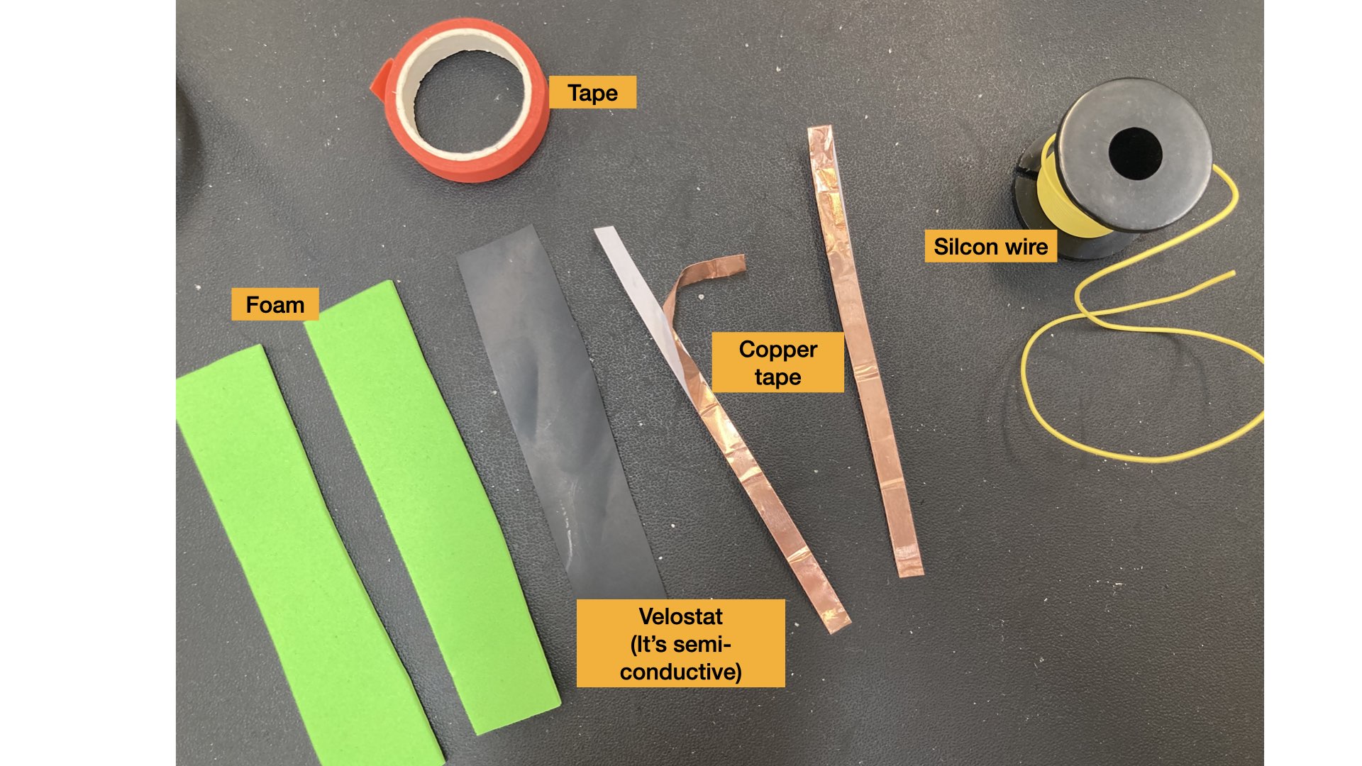
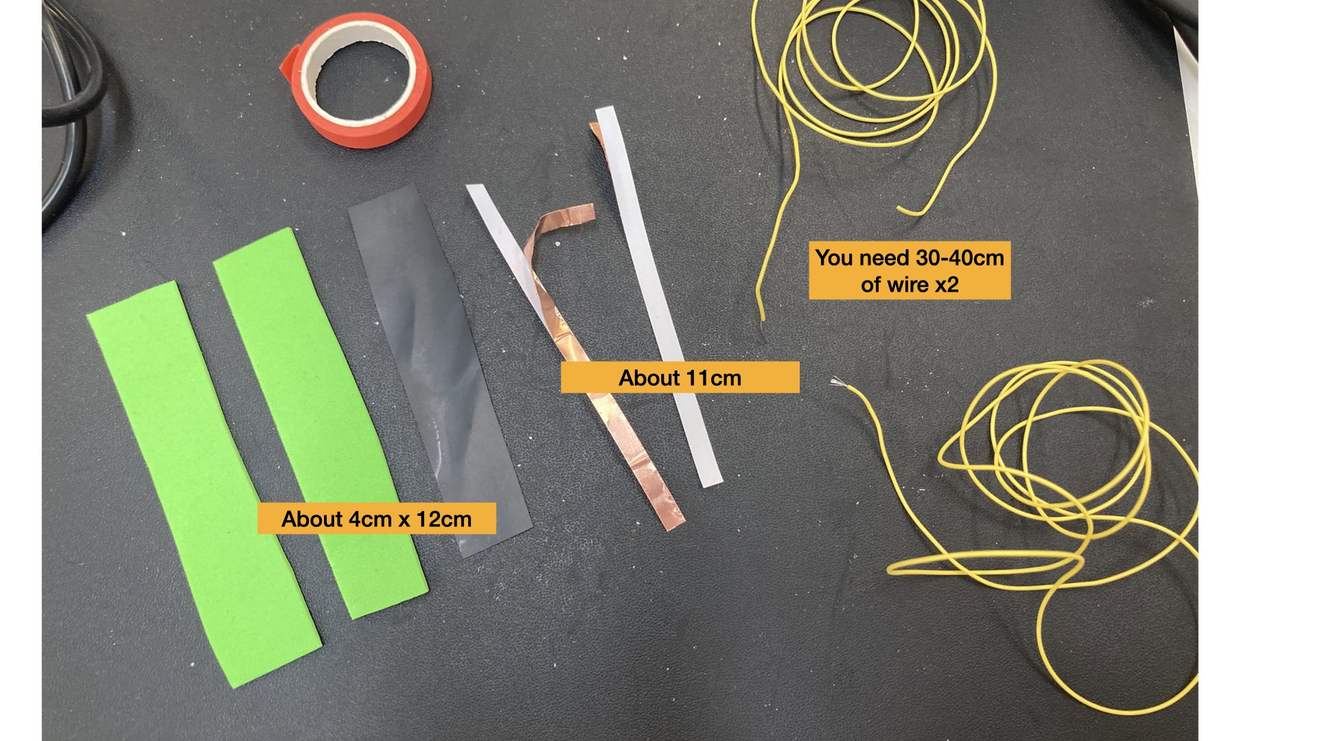
You will need:
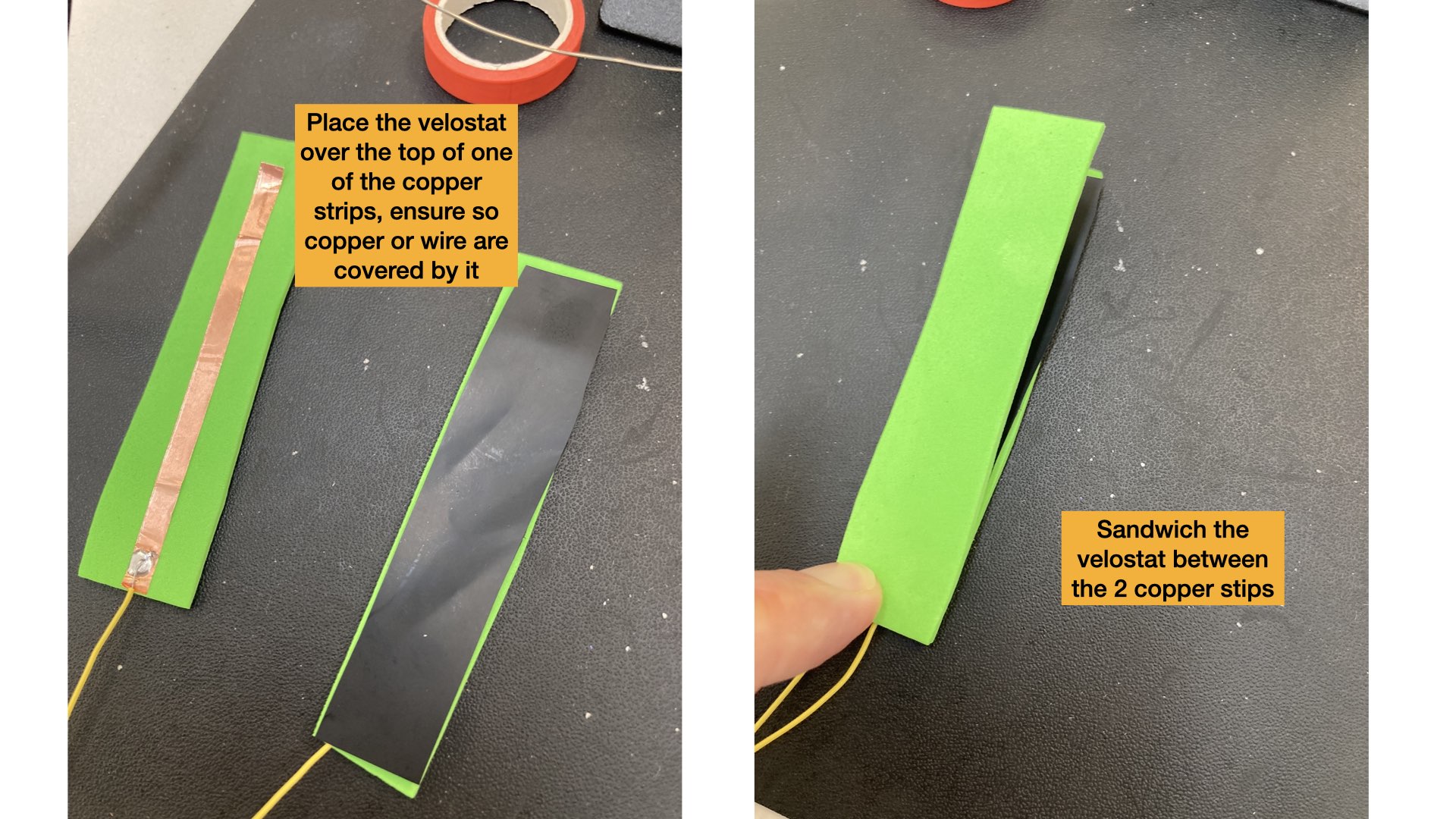
- Velostat
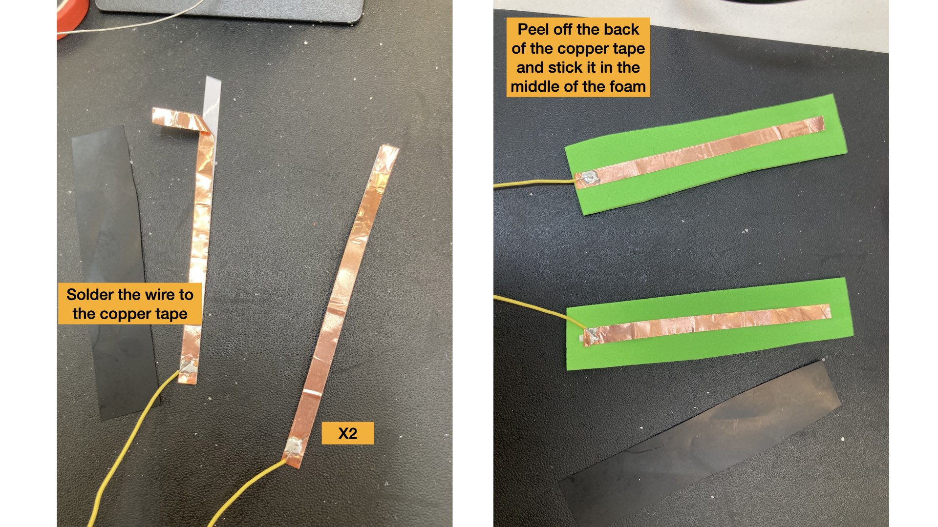
- Copper tape
- Foam
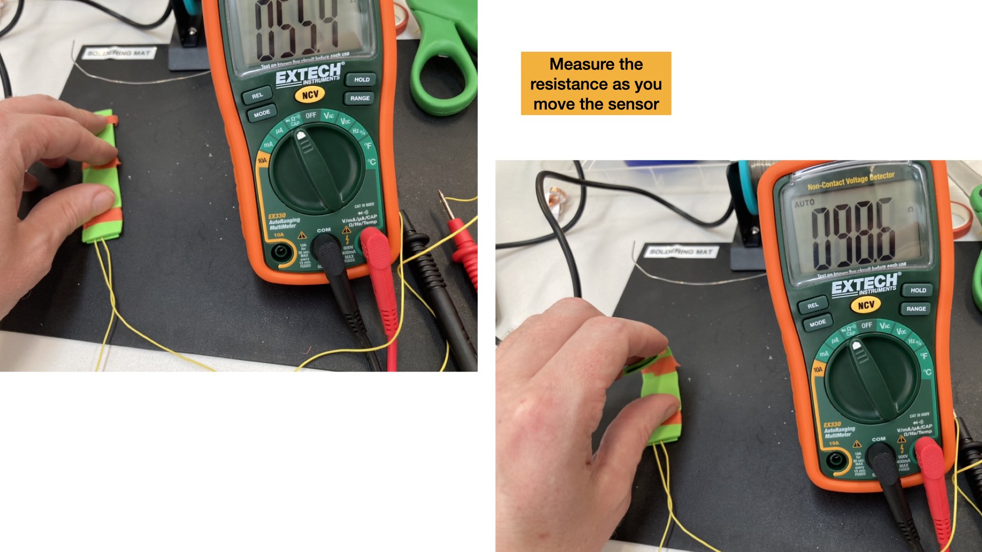
- Soldering kit
- Silicon wire (thin threaded wire is also fine)
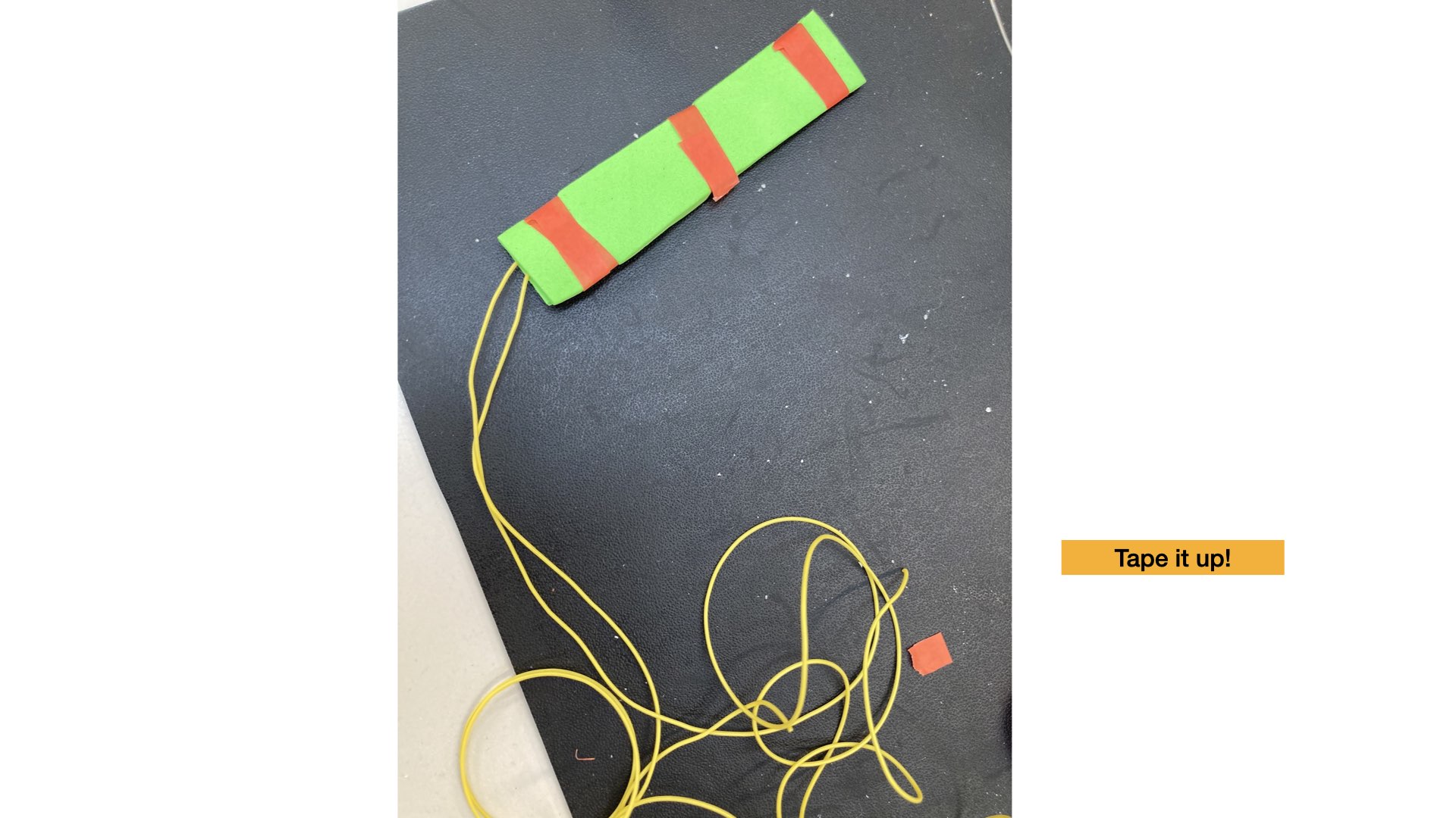
- Tape of some sort
Arduino wiring:
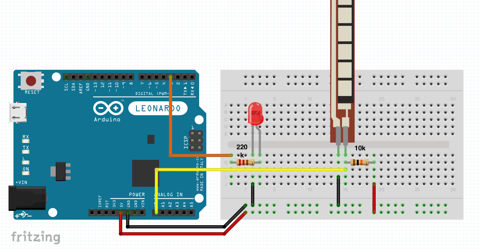
Arduino code:
/*

Simple code to light up an LED based on resistance sensor
Matt Jarvis - Creative Computing  Institute

*/

int ledPin = 3;   	// pin 3 has PWM
int flexPin = A0; 	// pin A0 is analog input

int value; 				// save analog value


void setup(){
  pinMode(ledPin, OUTPUT);  //Set pin 3 as 'output'
  Serial.begin(9600);       //Begin serial communication
}

void loop(){
  value = analogRead(flexPin);         	// Read and save analog value from resistor device
  Serial.println(value);               	// Print value to serial
  value = map(value, 700, 900, 0, 255);	// Map value from analogue (0-1023) to digital (0-255) (PWM)
  analogWrite(ledPin, value);          	// Send PWM value to led
  delay(100);                          	// Small delay
}