Workshop: Knitted Synthesisers
These notes are based on a workshop run by Agnes Cameron, and were developed as part of B Claxton and Eva Sajovic's Hack'n the Knit workshop series. These instructions are based on a tutorial for making two-stage astable oscillators on the website Electronics Tutorials, which also gives a lot more information on the electronic theory.
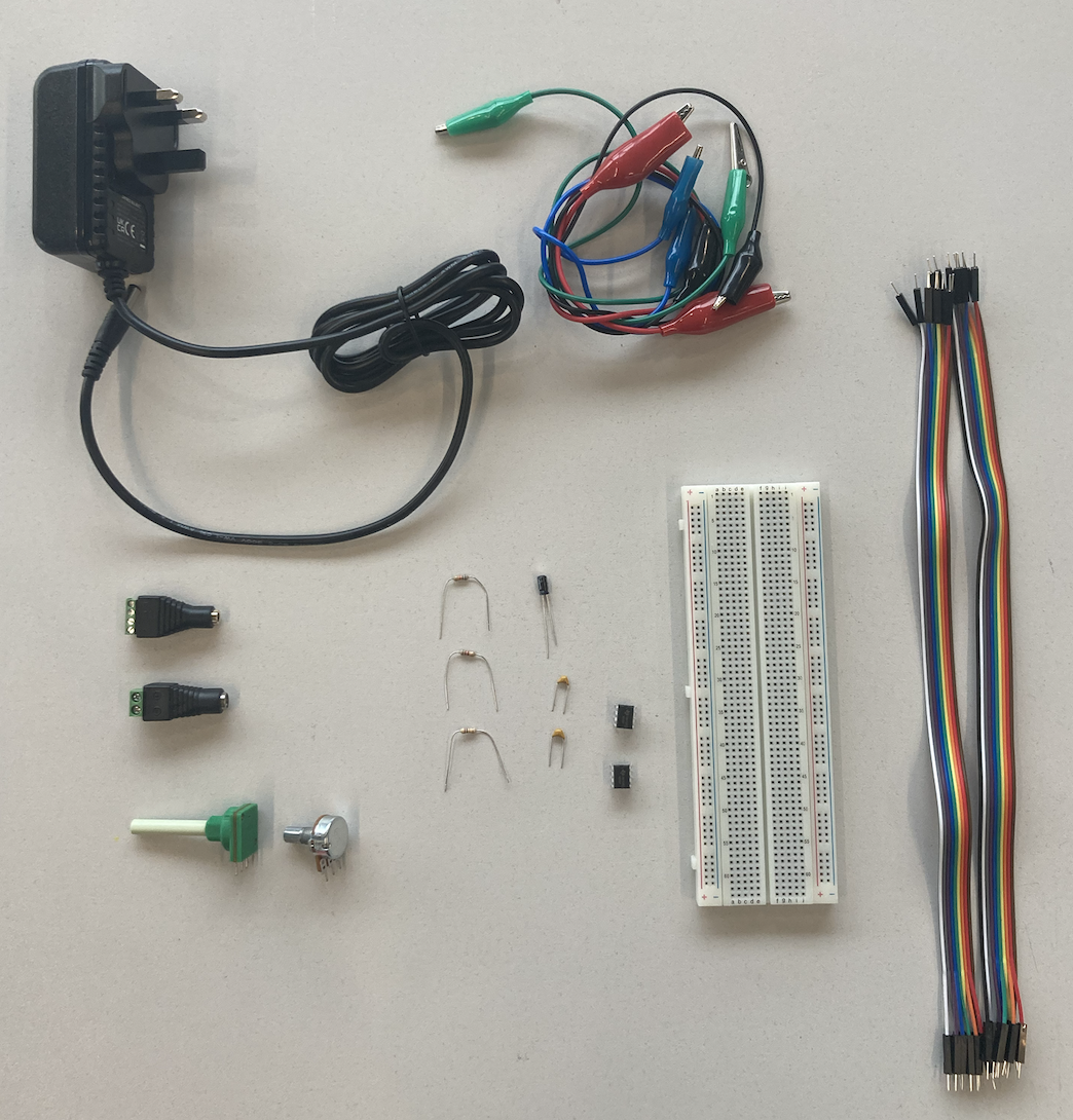
you will need
- 3.5mm jack breakout (socket)
- a speaker or pair of headphones
- a breadboard
- 2x 555 timers
- jumper wires
- 5V power supply
- 4 crocodile clip cables
- a 100kΩ resistor
- a 10kΩ resistor
- a 10kΩ variable resistor
- a 100kΩ variable resistor
- a 10$\mu$F capacitor
- a 100nF capacitor
- some conductive knit samples
Theory
making waves
Electrical signals travel round circuits as 'waves' -- signals that carry information. In the simplest circuits, these waves don't change at all -- the circuit is simply on or off. In circuits used to make noises, however, waves change constantly -- it's the changes in the wave that are what creates noise. The way a speaker works is to take one of these changing waves and pass the signal into a coil of wire. If brought close to a magnet, the coil of wire vibrates, making sounds! The circuit we are making in this tutorial allows us to create and change a wave using simple electronic components.
waves and sounds
The kind of sound a wave makes depends on two key things: the frequency (how often the wave changes, or oscillates per second), and the amplitude (how 'big' the wave gets). The frequency of the wave determines the pitch: a high-frequency wave (lots of oscillations per second) is a high pitch, and vice versa. The amplitude determines the 'loudness' of the wave. A wave with a changing frequency will sound like a changing note.
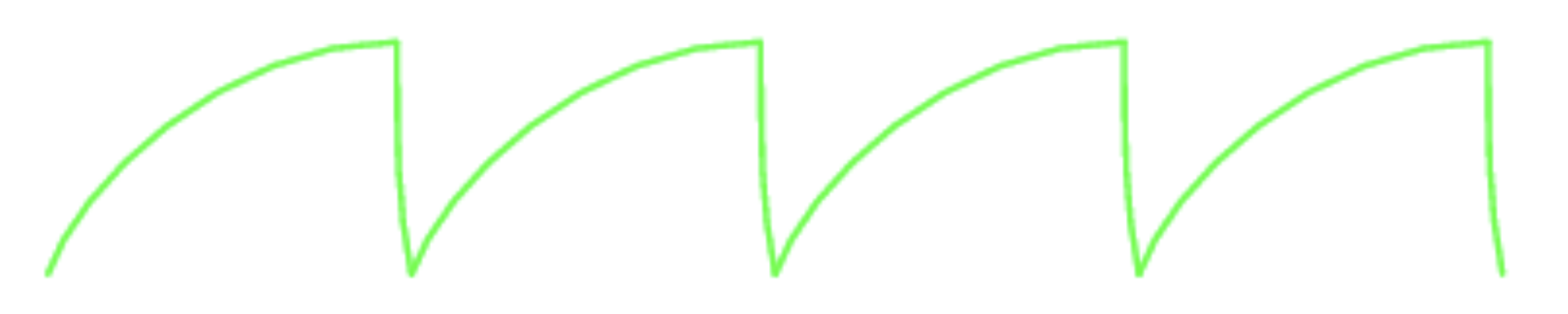
After this, there's a bunch of different things that can change the quality of the sound. Often this has a lot to do with the shape of a wave. The wave that comes out of a simple resistor-capacitor (RC) timing circuit is called a sawtooth wave -- these sound pretty unpleasant! We're going to use another component -- a 555 timer -- to make a square wave. These sound much cleaner.
resistors and capacitors
The most important components that determine how this circuit behaves are called resistors and capacitors. A resistor is something that resists the flow of electrical current, making it harder for current to pass through. You could think of it as a pipe which can be quite wide (low resistance) or very narrow (high resistance).
A capacitor collects electrical charge, meaning that as current flows into the capacitor, the voltage at the top of the component will slowly increase. When the voltage goes above a certain value, all of the charge will drain out through the capacitor and flow into ground. The bigger the capacitor, the longer this takes -- kind of like an electronic bucket.
When used together, these components can be used to make a very simple timing circuit -- current flow through the resistor can be controlled, changing the amount of time it takes for the capacitor to fill and empty. If we measure the voltage across the capacitor over time, we can see that it times in a regular interval: this becomes the basis for our sound wave! Smaller resistors = faster oscillation = higher pitch.
the astable multivibrator
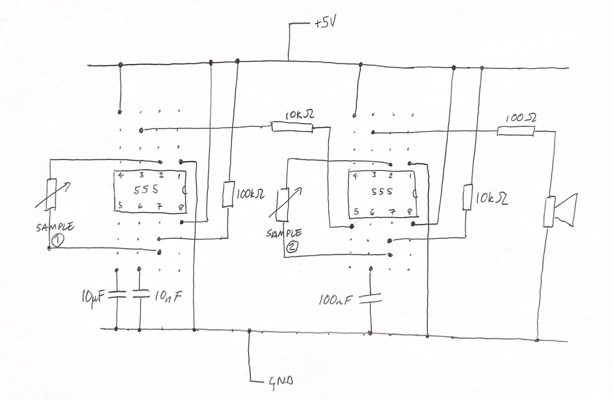
The circuit given by the diagram below is the one we're going to make! It's called 'astable' because it's a circuit that switches between two states -- the switching is what makes our sound wave. The diagram below contains two timing circuits -- those parts are the pairs of resistors and capacitors. The signal on the capacitor goes into Pin 3 of the 555 timer -- this signal 'times' the component, which produces a much cleaner wave on the output. Further in this document are photos of what the circuit looks like assembled.
This circuit has 2 stages, to allow us to make more interesting sounds! The first stage 'modulates' the second, mixing the waves together.
variable resistors
Lots of synthesisers use variable resistors to control the sounds that are made, by changing the speed of the timing circuit. Typically these are rotating dial components, but anything with a changing resistance can be used to change sounds. This brings us to...
variable resistors and conductive yarn
Typically, conductive yarn is used differently to conductive thread: it has much higher resistance, which means that it's not used to directly connect components unless they are very close together. However, because the conductive properties of fabrics knitted with conductive yarns change according to the state of the material, they make great sensors.
When a knitted sample is relaxed, it has a high resistance as the fibres in the yarn do not make contact with one another, meaning that current can pass only along a few strands. When the sample is stretched, however, the fibres are pulled into closer contact, reducing the resistance and allowing the flow of an electric current. This means that the inclusion of a conductive yarn allows you to sense movement in the material, creating a stretch sensor.
Practice
knitting with conductive yarn
To develop sensitive patches, I like to mix one strand of conductive yarn with one strand of regular cotton/lambswoll yarn. This has the effect of spacing out the conductive threads, making the patch’s resistance change more as it is stretched and relaxed.
measuring the resistance of a sample
Attach the crocodile clips to the edge of the sample, and connect the other ends to the multimeter. Move the wheel of the multimeter to the setting with the Ω symbol, and press the 'mode' button until you also see a Ω on the screen.
Once the system is connected, you should see a reading of the sample's resistance on the multimeter. Try stretching the sample and the number should decrease! Note that the letters next to Ω refer to the magnitude: k stands for 'kilo' (x1000), and M stands for 'mega' (x 10,000). You want your sample to be at least a few kΩ for this to work.
circuit diagrams
On a chip like the 555 timer, pins are numbered from 1-8, and are numbered counter-clockwise, beginning with the pin to the left of the notched end. On the circuit diagram, pins don't appear in this order -- this allows the wires to be represented without needing to cross over one another, but can be confusing when translating into reality.
breadboards for circuit layout
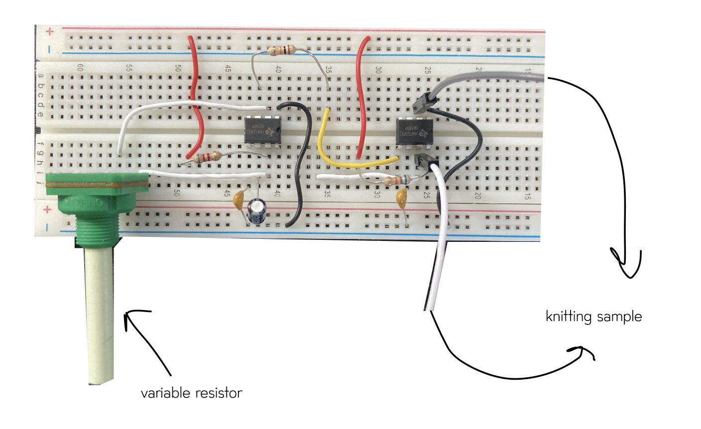
Breadboards are really useful tools for electronic prototyping, used to connect components together without any soldering. The legs of components are placed in holes on the board: in the middle of the breadboard, these are connected together vertically -- at the top and bottom they’re connected horizontally in long rails.
Here’s how the circuit from the diagrams above looks when wired into a breadboard:
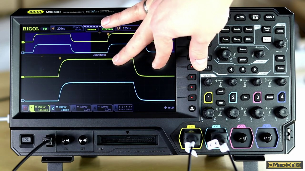
using an oscilloscope for debugging
A really helpful tool when making these kinds of circuit is an oscilloscope -- this allows us to see a visual representation of what the wave looks like in the circuit at different times!
In the CCI we have a RIGOL MSO5072 Oscilloscope, which is used for analysing electronic circuits. If you've not used an oscilloscope before it's worth being shown this by one of the technicians (either Tom or Agnes), but if you have used one before, the layout is not too dissimilar to other mixed-signal oscilloscopes.