
All about wire: what to use and when to use it!
All about wire: what to use and when to use it!
(Very quick version: if it leaves the board (stripboard, breadboard, PCB) use strand-core, if it connects points on same board use solid-core!)
Why does it matter what kind of wire I use?
Some of the time, it doesn't!
In fact, a lot of the time the differences don't matter at all, after all, if it's wire, it will conduct electricity...right?
Well, yes, but the deeper you get into complex projects, the more the differences start to matter. And when working on projects that might be a little power hungry, the difference between one kind of wire and another becomes safety critical!
As a beginner, having at least a casual knowledge of when those differences matter can avoid a lot of headache!
The short answer is: if it is wire, it will work. But it might set on fire, burn your house down, burn your fingers, damage your equipment, create uneccessary work, annoy your collaborators, waste time and waste money!
Different kinds of wire
There are an infinite number of kinds of wire and the differences can be pretty subtle, but really it all boils down to 2 categories: solid core and strand core.

Solid core contains a single strand (or core) of wire. It generally has lower internal resistance for its size and is cheaper. It is good for permanent installations, stripboard connections and breadboard jumpers.
Strand core (also known as flexi-core) contains multiple smaller strands of wire twisted together within the sheathing. It is good for connections which will move around as it does not break under mechanical stress.
A further consideration is sheath material, also known as insulation. It comes in different colors, which is important for communicating to others what a wire may be doing! They also come in many materials and thicknesses. PVC is the most common but silicon is often used too. Silicon is more flexible and heat resistant, whereas PVC is generally cheaper.
Wire gauges, cross-sectional area and more
It is important to choose the correct thickness of wire for a project. Thin wires can handle less current whereas thicker wires can handle more current.

Think of it like a pipe: the wider the diameter of the pipe, the more water can flow through it over a certain period of time. Current behaves in the same way. If we try to force a lot of water into a thin pipe, pressure builds up and eventually the pipe may burst. With electrical current, if the wire is too thin and the current is too high, instead of pressure build up the current fighting the internal resistance of the wire will cause heat build up. This heat build won't 'burst' the wire, but it can start a fire or even vaporise the wire!
Voltage drop
Thinner wires also suffer from 'voltage drop' over long lengths. This is because the wire starts to act like a resistor when it is long enough and some current and voltage is lost as it travels down the length.
Wire 'gauge' units
The term 'gauge' in the context of measurement usually refers to thickness; this is the case here. There are multiple different units used to quantify the thickness of a wire. The 2 most common you are likely to see are American Wire Guage (AWG) and cross-sectional area, which both work in slightly different ways.
A little history on AWG: American Wire Gauge is a pretty old measurement system. It's been used since the 1850s! It may seem backwards too because the thinner the wire the larger the number. Plus what even are those units anyways? Meters? Inches? Nautical miles?? Actually, the numbers reveal how the wire was manufactured. In order to make a length of wire, manufacturers had to 'draw' the copper through a pair of drawing dies to create a wire at a given thickness. The number of times the wire had to be drawn to acheive a certain thickness corresponds to the American Wire Gauge number...apparently.

For AWG the lower the number, the thicker the wire. For cross-sectional area, the higher the number, the thicker the wire!
Here's a table showing the conversion between the two:
| AWG | Cross-sectional area (mm2) |
|---|---|
| 16 | 1.31 |
| 18 | 0.823 |
| 20 | 0.519 |
| 22 | 0.352 |
| 24 | 0.205 |
| 26 | 0.128 |
| 28 | 0.0804 |
| 30 | 0.0503 |
Calculating the thickness of wire you will need can be done using this formula:
A = (2 * L * I * p) / V
- A: cross-sectional area in meters2 your will need to be
- 2: this coefficient accounts for the 'round trip': if your cable is 1 meter long from source to load and load back to ground is 2 meters!
- L: the length in meters that the wire will be
- I: the current in amps it will need to carry (it is good practice to add some margin here)
- p: the resistivity (in ohm-meters) of the material the wire is made of. Most wires are copper which is about 0.000000017 ohm-meters, more commonly expressed as 1.68 * 10-8 (this figure varies with temperature, but is close enough for our purposes)
- V: this is the acceptable voltage drop (in volts), ideally 3% or less, over the length. For example if the working voltage is 10V and the acceptable drop is 3% then this figure would be 0.3V
Example:
We have a cable of 0.5m powering a DC motor that consumes 400mA at 5V, the acceptable voltage drop is 2% or 100mV. We calculate the wire thickness as follows:
Cross-sectional area = (2 * 0.5 * 0.4 * 0.000000017) / 0.1 = 0.000000068m² or 0.068mm²
From the table above we can see that we could just about get away with 28 AWG, but we'd probably choose 26 AWG to be on the safe side. Remember: this figure only works with a wire length of 0.5m! If you increased the length, you would need thicker wire so recalculate in this case!
The general rule is that if the load is low and the wires are short, no need to worry. However, if the load is high or the wire length needs to be long, then wire thickness becomes very important. We recommend using this calculator when designing projects using lots of motors, LEDs or other high current devices...or calculate with the formula above!
Colour conventions
This may seem a little arbitrary, but while the colour of the sheathing on your wire doesn't affect it's performance, choosing carefully is critical! Colour coded wires will help with reducing complexity, troubleshooting, collaborating, protecting against human error and improve safety.
As working with electronics is often collaborative we tend to use established conventions when choosing wire colours. This is very important, but can be a little tricky as the meaning of a colour can sometimes change with the context you are working in.
Below are some conventions that are mostly universal to the world of physical computing.
⚠ Safety Note: these are only conventions, they do not guarantee the function of a wire only provide a hint. Always check documentation, do not assume! ⚠
| Colour | Function |
|---|---|
| BLACK | Ground. One exception is US mains wiring where this means live! |
| BROWN | Sometimes GND, sometimes VCC, watch out for this one! |
| RED | VCC or positive voltage |
| BLUE | Negative voltage. Commonly seen in audio circuits |
| GREEN | Usually data of some kind. When paired with a yellow wire it is usually SDA line of i2C bus |
| YELLOW | Often a serial clock. When paired with a green wire it is usually SCL line of i2C bus |
The quick guide to choosing suitable wire
Here's a quick list of things to think about when choosing wire for a part of your project. More details are given in the following sections.
⚠ Safety Note: using this checklist is not the same as calculating the suitability of the wire you use in a project. It is just an overview, always consider the load you put down wires carefully! ⚠
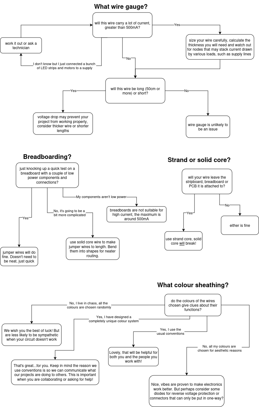
See below for more details or if you prefer plain text!
- Will this wire carry more than around 500mA of current? (this is an approximation)
- No
- Wire gauge is unlikely to be much of an issue as long as the wires are short (less than 30cm)
- Yes
- Size your wires carefully, calculate the thickness with the above formulas and be careful for nodes where the load is higher due to current draw from several loads. For example, on your power lines.
- I don't know, but I just hooked up a load of motors and lights to a power supply
- Turn it off, work out the current draw or ask a technician for help
- No
- Will this wire be long or short? Greater than about 50cm?
- Yes, it's a long run
- Voltage drop starts to become a consideration, particularly for sensors. Consider increasing your wire guage or even better, calculate it!
- No, I'm just connecting between a couple of breadboards/stripboards/breakouts
- Wire gauge and voltage drop are unlikely to be an issue here
- Yes, it's a long run
- Are you knocking up a quick test on a breadboard with a couple of low power components and connections?
- Yes, I'm just trying out a quick idea
- Great, use jumper wires or offcuts from the solid core bin. It doesn't need to be classy, the main thing is to get something working!
- No, it's probably going to be a little more complicated than that
- In that case, use solid core wire to make jumper wires to length. Bend them into shapes for neater routing. This will make it easier to see what's going on, cut down on overcrowding and reduce the chance of crappy jumper wires introducing noise into your circuit (which is a pain to diagnose!)
- Pro Tip: always keep the solid core jumper wires you make. Ask a technician for a baggy to keep them in and guard them with your life; they are extremely precious! When you next come to making a breadboard circuit you will be happy you have them: now you can be both quick and neat!
- In that case, use solid core wire to make jumper wires to length. Bend them into shapes for neater routing. This will make it easier to see what's going on, cut down on overcrowding and reduce the chance of crappy jumper wires introducing noise into your circuit (which is a pain to diagnose!)
- No, I will be using a fair bit of power (greater than 500mA at a single node)
- DO NOT USE A BREADBOARD OR JUMPER WIRES! Neither breadboards or jumper wires are designed for taking large amounts of current and using them in that way is a fire risk!
- Go back to the drawing board and calculate how much power you would be sending down wires and through the breadboard or consult a technician if unsure
- DO NOT USE A BREADBOARD OR JUMPER WIRES! Neither breadboards or jumper wires are designed for taking large amounts of current and using them in that way is a fire risk!
- Yes, I'm just trying out a quick idea
- Does your wire leave the strip board or PCB is attached to, or is it just connecting points on the same board?
- Yes, it leaves the board
- Always use stranded wire! Solid core wire does not handle mechanical stress well and will break!
- Consider 'tinning' the ends with solder if you need to attach it to screw terminals or crimp pins/sockets on for connecting into header pins/sockets (see the Crimping Guide)
- No, it's just connecting points on the same board
- Stranded or solid is fine. However solid core is generally easier to get through stripboard/PCB holes and can be bent into shapes to route cables more neatly. (solid core wire is also excellent for neater breadboard layouts for the same reason!)
- Yes, it leaves the board
- Does the colour of the wire give helpful clues about what it does?
- No, I live in chaos and choose colours completely at random.
- We wish you the best of luck! And are unlikely to be that sympathetic when you reverse power your project or are completely baffled about why it isn't working...chances are we will have some trouble helping you figure it out too!
- Yes, I use my own system that is completely unique and has no relation to any established convention
- That's great...for you. At least you're using some kind of system, but the reason we like conventions is that it allows us to communicate what our project is doing to others. This is important when you are collaborating or asking for help
- Yes, I use the usual conventions: black = GND, red = VCC etc.
- Lovely, that will be helpful for both you and the people you work with!
- No, all my cables colours are chosen according to aesthetic reasons \m/(>_<)\m/
- Nice, vibes are proven to make electronics work better. But perhaps consider some diodes for reverse voltage protection or connectors that can only be put in one-way?
- No, I live in chaos and choose colours completely at random.
Conclusion
For the most part, choosing what wire to use is pretty simple. Just grab some solid-core for breadboarding or stripboarding that'll fit in the holes and grab stranded for anything else that will fit in your terminal blocks or whatever you're stuffing it into!
However, it's incredibly valuable to know when it can be not as simple, even if you never find yourself in those situations. And having the knowledge on hand when you do need to run higher current or longer distances is extremely handy!